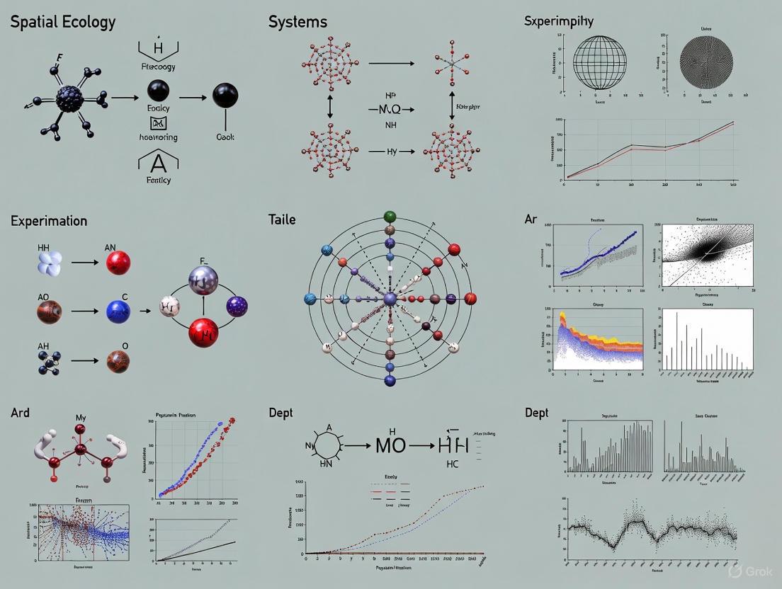
Navigating the Complexities: Key Challenges in Spatial Ecology Experimentation and Their Impact on Biomedical Research
Spatial ecology experimentation is pivotal for understanding complex biological systems, from ecosystem biodiversity to drug mechanisms of action within tissues.
Navigating the Complexities: Key Challenges in Spatial Ecology Experimentation and Their Impact on Biomedical Research
Abstract
Spatial ecology experimentation is pivotal for understanding complex biological systems, from ecosystem biodiversity to drug mechanisms of action within tissues. This article explores the foundational, methodological, and analytical challenges inherent to this field, drawing direct connections to applications in drug discovery and development. We examine core obstacles such as environmental multidimensionality, the Modifiable Areal Unit Problem (MAUP) in data analysis, and the integration of complex spatial data. For researchers and drug development professionals, we detail practical strategies for troubleshooting experimental design, optimizing technological applications like mass spectrometry imaging and spatial biology platforms, and validating findings through standardized frameworks and multimodal data integration to enhance reproducibility and translational impact.
The Core Hurdles: Understanding the Theoretical and Environmental Complexities of Spatial Systems
Embracing Multidimensionality and Combating Combinatorial Explosion
Frequently Asked Questions (FAQs)
FAQ 1: What is combinatorial explosion and why is it a critical problem in spatial ecology experiments?
Combinatorial explosion refers to the rapid growth of complexity that occurs when the number of unique experimental treatments increases exponentially with each additional environmental factor being tested [1]. In spatial ecology, this creates a fundamental research limitation because testing interactions between multiple stressors—such as temperature fluctuations, precipitation gradients, and soil quality variations—requires an unmanageable number of experimental combinations [1]. This problem is particularly acute when studying complex spatial phenomena like savanna-forest transitions, where crossing multiple bifurcation points in ecological systems creates rich, complex patterns that are difficult to model and test experimentally [2].
FAQ 2: What practical methods can researchers use to manage combinatorial complexity in multi-stressor experiments?
The most effective approach involves using response surface methodologies where two primary stressors are identified and systematically varied to create response landscapes rather than traditional one-dimensional response curves [1]. This technique allows researchers to model complex interactions while maintaining experimental feasibility. Additionally, employing dimension reduction techniques and clustering in spatial data analysis can help identify key variable interactions before designing complex experiments [3].
FAQ 3: How can visualization tools help researchers comprehend multidimensional spatial data without cognitive overload?
Modern geovisualization tools like Variable Mapper enable simultaneous visualization of up to six variables in a manageable format, using techniques such as small multiples, coordinated views, and interactive filtering [3]. These tools help researchers identify spatial patterns across multiple variables while managing the cognitive load, as human visual perception is typically limited to distinguishing four to six variables simultaneously [3]. Effective multivariate visualization combines color, size, rotation, and other visual variables to represent different data dimensions on spatial maps [4].
Troubleshooting Common Experimental Challenges
Problem 1: Inability to discern meaningful patterns from complex multivariate datasets.
Solution: Implement visual clustering techniques and dimension reduction methods before detailed analysis. Use tools that support side-by-side comparison of spatial variables through small multiple maps, which facilitate pattern recognition across multiple dimensions without visual overload [3]. For spatial data, ensure your visualization tool uses coordinated views where selections in one visualization automatically filter representations in others.
Problem 2: Experimental designs becoming unmanageably large with multiple environmental factors.
Solution: Adopt a response surface methodology focusing on two primary stressors initially, then sequentially add dimensions [1]. Utilize fractional factorial designs that test the most critical interactions rather than full combinatorial spaces. Implement adaptive experimental designs that use early results to refine subsequent treatment combinations.
Problem 3: Difficulty representing more than three variables simultaneously in spatial analyses.
Solution: Employ multivariate visualization techniques that combine multiple visual variables such as color, size, and rotation [4]. For example, representing weather data with rotation for wind direction, size for wind speed, and color for temperature enables effective representation of three data dimensions simultaneously [4]. Ensure sufficient contrast between visual elements and avoid color combinations that impair interpretation.
Experimental Protocols for Multidimensional Research
Protocol 1: Response Surface Methodology for Multiple Stressors
- Identify Primary Stressors: Select the two most significant environmental factors based on preliminary studies or literature review [1]
- Design Gradient Treatments: Establish 5-7 gradient levels for each primary stressor rather than simple presence/absence treatments
- Measure Response Variables: Record ecological responses at each combination point, focusing on key metrics like biodiversity indices, population densities, or physiological measurements
- Construct Response Surface: Use interpolation techniques to create a continuous response landscape from discrete measurements
- Validate Model Predictions: Test model predictions at intermediate points not included in initial experimental design
Protocol 2: Spatial Gradient Analysis Across Environmental Transitions
- Site Selection: Identify natural environmental gradients such as rainfall gradients, elevation transects, or urbanization intensity gradients [2]
- Sampling Design: Establish sampling points along the gradient continuum with appropriate replication
- Multivariate Data Collection: Record both environmental variables and ecological responses at each sampling point
- Spatial Pattern Analysis: Use spatial statistics to identify transitions, thresholds, and nonlinear responses along gradients
- Model Fitting: Apply spatial autoregressive models or generalized additive models to characterize responses to multiple simultaneous gradients
Experimental Workflow Visualization
Data Management Strategy for Complex Experiments
Quantitative Complexity of Combinatorial Experiments
Table 1: Growth of Experimental Complexity with Additional Factors
| Number of Factors | Number of Treatment Levels | Possible Unique Combinations | Experimental Feasibility |
|---|---|---|---|
| 2 | 3 each | 9 | High |
| 3 | 3 each | 27 | Moderate |
| 4 | 3 each | 81 | Challenging |
| 5 | 3 each | 243 | Limited |
| 6 | 3 each | 729 | Impractical |
Table 2: Comparison of Experimental Design Strategies for Multidimensional Ecology
| Design Approach | Variables Accommodated | Combinatorial Control | Implementation Complexity | Analytical Power |
|---|---|---|---|---|
| Classical ANOVA | 2-3 factors | Limited | Low | Moderate |
| Response Surface | 2 primary + 2 secondary | High | Moderate | High |
| Fractional Factorial | 4-6 factors | Moderate | High | Moderate |
| Gradient Analysis | Natural environmental variation | High | Low | High |
Research Reagent Solutions for Spatial Ecology
Table 3: Essential Resources for Multidimensional Spatial Ecology Research
| Resource Category | Specific Tool/Technology | Function in Research | Application Context |
|---|---|---|---|
| Environmental Sensors | Automated data loggers | Capture environmental variability | Field measurements across spatial gradients |
| Spatial Analysis Software | GIS with multivariate capabilities | Visualize and analyze spatial patterns | Identifying savanna-forest boundaries [2] |
| Statistical Platforms | R with spatial packages | Model complex interactions | Response surface analysis [1] |
| Visualization Tools | Variable Mapper | Simultaneous display of multiple variables | Exploring urban superdiversity and liveability [3] |
| Experimental Systems | Mesocosms with environmental control | Test multiple stressor interactions | Aquatic ecosystem responses to global change [1] |
Confronting Spatial Heterogeneity and Environmental Gradients
Technical Support Center
Troubleshooting Guides & FAQs
Q1: Our experimental tiles for testing substrate heterogeneity are showing inconsistent community colonization compared to controls. What could be the cause? A: Inconsistent colonization is often due to unintended variations in tile surface area or material. The experiment in Bracelet Bay used paired 15x15cm limestone tiles where heterogeneous tiles had pits drilled into them, but the total surface area was statistically indistinguishable from the flat control tiles due to natural variability from manual cutting [5]. Ensure your manufacturing process is standardized. Also, verify that you are regularly clearing surrounding canopy algae (like fucoids) from the tiles, as these can alter local conditions such as temperature and wave disturbance, leading to confounding effects [5].
Q2: We are seeing high variability in population stability metrics across our heterogeneous experimental units. Is this expected? A: Yes, this can be expected. Heterogeneity creates refugia that enhance population stability for some stress-sensitive species [5]. However, it can also suppress dominant species and consumers, which might otherwise have a stabilizing effect on the community [5]. Therefore, the net effect on stability is the result of these counteracting pathways. Your results may show high variability as these opposing forces (both stabilising and destabilising) play out.
Q3: What is the best method for sampling community cover on experimental tiles to capture both canopy and understorey species? A: Employ a stratified sampling approach using image analysis [5]. This involves:
- Canopy Species: Take pictures and measure species cover using image analysis software (e.g., Adobe Photoshop) [5].
- Understorey Species: Take separate pictures for the understorey and estimate species cover using point-count image subsampling. Identify all organisms beneath a standard grid of points (e.g., 500 points per image) [5].
Q4: How long should a field experiment on heterogeneity and community stability run to yield reliable data? A: Multi-year data is crucial to capture temporal stability and account for seasonal variations and long-term community dynamics. The foundational experiment in this field ran for 35 months, with seasonal sampling yielding 11 time points per experimental unit [5]. A minimum of 2-3 years is recommended for assessing multi-year temporal stability.
Experimental Protocol: Testing Heterogeneity Effects on Rocky Shores
Title: Protocol for Assessing Community Stability on Artificial Substrates of Varying Heterogeneity.
Objective: To quantify the effects of small-scale substrate heterogeneity on the temporal stability of intertidal communities along an environmental stress gradient.
Methodology Summary:
This protocol is based on a 35-month field experiment conducted on a rocky shore [5].
Tile Preparation:
- Create paired sets of experimental tiles from a consistent material like limestone.
- Non-heterogeneous Tiles: Flat, smooth-surfaced tiles (15cm x 15cm).
- Heterogeneous Tiles: Tiles of the same dimensions with a standardized configuration of large, medium, and small pits drilled into them to mimic natural topographic variation [5].
- Critically, verify that the total surface area does not differ significantly between the two tile types, ensuring the test is of heterogeneity, not area.
Experimental Deployment:
- Select a site with a clear environmental gradient (e.g., an intertidal zone with emersion stress from high to low shore).
- Deploy tile pairs (one flat, one pitted) at multiple stations (e.g., 35 stations) along several transects within the study area [5].
- Secure tiles to exposed rock surfaces.
Site Maintenance:
- Regularly clear canopy-forming algae (e.g., fucoids) from the immediate area surrounding the tiles to prevent them from altering tile conditions through shading, whiplash, or wave attenuation [5].
Data Collection:
- Sample tiles seasonally during low tide over multiple years.
- Use the stratified image analysis method described in FAQ #3 to quantify percent cover of all species in both canopy and understorey strata [5].
Data Analysis:
- Calculate temporal stability metrics for populations and the entire community.
- Use structural equation modelling (SEM) to disentangle the contributions of different pathways through which heterogeneity affects stability (e.g., species richness, asynchrony, dominance, consumer pressure) [5].
Table 1: Counteracting Pathways Through Which Heterogeneity Influences Community Stability [5]
| Pathway | Effect on Stability | Proposed Mechanism |
|---|---|---|
| Provision of Refugia | Increases | Buffers environmental disturbances, enhancing population-level stability for stress-sensitive species. |
| Increased Species Richness & Asynchrony | Increases | Creates varied niches, supporting more species whose asynchronous fluctuations buffer community-level variability. |
| Reduction of a Dominant Species | Decreases | Heterogeneous niches reduce competitive exclusion, suppressing a dominant species that would otherwise stabilize community composition. |
| Suppression of Consumers | Decreases | Physical patchiness disrupts predator movement and access to prey, reducing top-down control that can stabilize interactions. |
Table 2: Key Specifications from the Rocky Shore Heterogeneity Experiment [5]
| Parameter | Specification |
|---|---|
| Experiment Duration | 35 months (May 2019 - April 2022) |
| Sampling Frequency | Seasonal (11 time points per tile) |
| Tile Material | Limestone |
| Tile Dimensions | 15 cm x 15 cm |
| Number of Tile Pairs | 35 |
| Key Measured Variables | Species percent cover (canopy & understorey), population stability, species richness, asynchrony |
Experimental Workflow and Stability Pathways
The Scientist's Toolkit: Research Reagent Solutions
Table 3: Essential Materials for Rocky Shore Heterogeneity Experiments
| Item | Function |
|---|---|
| Limestone Tiles | Artificial substrates that serve as standardized, replicable surfaces for community colonization and experimental manipulation (e.g., drilling pits for heterogeneity) [5]. |
| Pitted/Heterogeneous Tiles | Experimental units with drilled pits that create topographic heterogeneity, mimicking natural microhabitats and providing refugia from environmental stress [5]. |
| Digital Camera | Equipment for capturing high-resolution images of experimental tiles for subsequent stratified analysis of canopy and understorey species cover [5]. |
| Image Analysis Software | Software (e.g., Adobe Photoshop) used to measure percent cover of canopy species from digital images and facilitate point-count subsampling for understorey species [5]. |
Frequently Asked Questions (FAQs)
1. What is the Modifiable Areal Unit Problem (MAUP) in simple terms?
The Modifiable Areal Unit Problem (MAUP) is a source of statistical bias that occurs when the results of your spatial analysis change based on how you choose to aggregate your point data into geographic units (like districts, census tracts, or grid cells) [6] [7]. It means that your conclusions can be influenced by the arbitrary scale (size) and shape of your analysis units, not just the underlying data itself [8] [9].
2. What are the two main components of MAUP?
MAUP manifests through two distinct effects [7]:
- The Scale Effect: Different results emerge when the same data is aggregated into units of different sizes (e.g., census tracts vs. counties) [6] [8].
- The Zoning Effect: Different results emerge when data is grouped into different configurations of units at the same scale (e.g., different arrangements of grid cells of the same size) [6] [10].
3. Why should spatial ecologists be concerned about MAUP?
MAUP is critical in spatial ecology because it can lead to spurious relationships and misinterpretations of spatial patterns [10]. For instance, the observed relationship between an environmental factor (like NDVI) and an ecological outcome can be artificially strong or weak depending on the spatial resolution and zoning of your data [10]. This can directly impact the effectiveness of management and conservation decisions [11].
4. How can I test if my analysis is sensitive to MAUP?
Conducting a MAUP sensitivity analysis is recommended [6]. This involves running your same analysis multiple times using different, equally plausible scales and zoning schemes. If your results or key parameters (like correlation coefficients) change significantly, your study is sensitive to MAUP, and you should report this uncertainty.
5. Are there any statistical solutions to MAUP?
While no single method completely eliminates MAUP, several approaches can help manage it. These include using Bayesian hierarchical models to combine aggregated and individual-level data, focusing on local spatial regression instead of global models, and developing scale-independent measures, such as those considering fractal dimension [6].
Troubleshooting Guides
Issue 1: Inconsistent or Unstable Correlation/Covariance Estimates
Problem: The correlation between two spatial variables (e.g., pollution levels and illness rates) changes dramatically when you analyze your data at different aggregation levels.
Diagnosis: This is a classic symptom of the scale effect of MAUP. Generally, correlation tends to increase as the size of the areal units increases [6].
Solution:
- Acknowledge the Problem: Do not report results from a single, arbitrary scale.
- Perform Sensitivity Analysis: Re-run your correlation analysis across a spectrum of scales (e.g., 50m, 100m, 200m, 500m grids) [11]. Report the range of correlation coefficients you obtain.
- Use Robust Methods: Consider correcting your variance-covariance matrix using samples from individual-level data, if available [6].
- Report with Transparency: Clearly state the scale(s) used in your analysis and the potential for MAUP-induced bias in your conclusions.
Issue 2: Model Outputs Lead to Misleading Management Decisions
Problem: Your habitat distribution models predict vastly different areas of suitable habitat at different spatial resolutions, leading to uncertainty about where to focus conservation efforts.
Diagnosis: This is a direct consequence of MAUP on model outputs and subsequent decision-making [11]. Coarser resolutions often lead to an oversimplification of the modelled extent.
Solution:
- Match Scale to Decision Context: Use coarse-resolution data for strategic, large-scale policy decisions, but insist on finer-resolution data for consenting or managing individual activities [11].
- Compare Model Performance: Evaluate your model's performance (e.g., AUC, precision) across multiple spatial resolutions. The table below illustrates how model performance and output can vary with resolution, using a marine conservation example [11]:
Table 1: Illustrative Example of Model Output Variation with Spatial Resolution for a Protected Marine Habitat
| Spatial Resolution | Model Performance (AUC) | Modelled Habitat Coverage (km²) | Suggested Use Case |
|---|---|---|---|
| 50 m | 0.89 | 15.5 | Local management & individual activity consenting |
| 100 m | 0.85 | 18.2 | Regional planning |
| 200 m | 0.82 | 22.1 | Regional planning |
| 500 m | 0.75 | 28.7 | National / strategic policy |
Issue 3: Suspected Zoning Effect (Gerrymandering in Analysis)
Problem: You suspect that the way boundaries are drawn (even unintentionally) is creating a false pattern or hiding a real one in your data.
Diagnosis: This is the zoning effect, where the configuration of boundaries at a fixed scale alters analytical results [8] [9]. This is analogous to gerrymandering in elections.
Solution:
- Test Alternative Zoning Schemes: If your data is aggregated into custom zones (e.g., watersheds, management areas), reconfigure them into several alternative, equally justifiable schemes and re-run your analysis.
- Use Non-arbitrary Units: Where possible, use zoning units based on "natural" boundaries relevant to your ecological question (e.g., based on income and unemployment levels in human ecology, or soil and elevation in landscape ecology) [9]. One study found that the relationship between pollution and illness was strongest in "natural neighborhoods" compared to government-delineated census tracts [9].
- Implement a Zoning Experiment: Systematically create multiple random aggregations of your base data at the same scale to quantify the variability introduced by the zoning effect [6].
Experimental Protocols for MAUP Investigation
Protocol 1: Quantifying the Scale and Zoning Effects
This protocol provides a methodology to empirically measure the impact of MAUP on your spatial dataset.
1. Hypothesis: The statistical relationship between variable X (e.g., nutrient load) and variable Y (e.g., algal bloom intensity) is sensitive to the scale and zoning of data aggregation.
2. Experimental Workflow:
3. Materials and Data:
- High-resolution point or individual-level data for your variables of interest.
- GIS software (e.g., ArcGIS, QGIS) with geoprocessing tools for aggregation.
- Statistical software (e.g., R, Python with Pandas/GeoPandas).
4. Procedure:
- For the Scale Effect: Using a grid-based approach, aggregate your base data into a series of regular grids of increasing cell size (e.g., 50m, 100m, 200m, 500m). For each grid, calculate the summary statistics of interest (e.g., global mean, correlation between variables, regression slope).
- For the Zoning Effect: Select one specific scale (e.g., 100m grid). Create several alternative aggregations by shifting the grid origin or by using alternative zoning systems (e.g., hexagons, watershed boundaries). Calculate the same statistics for each of these zoning schemes.
- Analysis: Plot the calculated statistics (e.g., correlation coefficient) against the scale of aggregation and across the different zoning schemes. The resulting variance demonstrates the influence of MAUP. Report the upper and lower bounds of your findings [6].
Protocol 2: MAUP-Sensitive Habitat Distribution Modeling
This protocol integrates MAUP testing into a standard species distribution modeling workflow.
1. Hypothesis: The predicted spatial extent and location of a key habitat are significantly affected by the spatial resolution of the input environmental data.
2. Workflow Diagram:
3. Materials:
- Species occurrence data (presence/absence or presence-only).
- Environmental predictor rasters (e.g., temperature, bathymetry, vegetation index) at their finest available resolution.
- Species distribution modeling software (e.g., MaxEnt, R packages
dismoorSDM).
4. Procedure:
- Resample all environmental predictor rasters to a common set of coarser resolutions (e.g., 50 m, 100 m, 200 m, 500 m) [11].
- Run your chosen distribution model (e.g., MaxEnt) separately for each set of resolution-matched predictors.
- For each model, record performance metrics (e.g., Area Under the Curve - AUC) and calculate the total area of predicted suitable habitat.
- As shown in Table 1, compare the results across resolutions. The divergence in predicted area and model performance highlights the MAUP's impact. Use this analysis to justify the choice of an appropriate, scale-specific model for your management objective [11].
Table 2: Key Research Reagent Solutions for Investigating MAUP
| Tool / Resource | Function in MAUP Research | Example Application |
|---|---|---|
| GIS Software (e.g., ArcGIS, QGIS) | To aggregate point data, create multiple zoning schemes, and perform spatial overlays. | Generating a series of grid layers at different resolutions for scale effect analysis [6]. |
| Spatial Statistics Packages (e.g., R 'spdep', Python 'PySAL') | To calculate spatial autocorrelation, local indicators of spatial association (LISA), and spatial regression. | Quantifying how spatial autocorrelation changes with aggregation scale [10]. |
| Scripting Language (e.g., Python with ArcPy/GeoPandas) | To automate the data simulation and re-aggregation process for robust sensitivity analysis [6]. | Running a Monte Carlo simulation to create hundreds of alternative zoning schemes. |
| Data Simulation Tools | To generate synthetic spatial data with known properties, allowing for controlled MAUP experiments [6]. | Isolating the effect of aggregation from other confounding factors present in real-world data. |
| Bayesian Hierarchical Modeling Frameworks (e.g., R 'INLA') | To integrate data from multiple levels of aggregation and provide a formal framework for accounting of uncertainty. | Combining fine-scale survey data with coarse-scale census data for ecological inference [6]. |
Moving Beyond Classical Model Organisms for Generalizable Insights
Frequently Asked Questions (FAQs)
What are the main advantages of using non-model organisms in research? Non-model organisms are invaluable for studying biological traits absent in classical models (e.g., regeneration in salamanders), evolutionary questions requiring specific phylogenetic positions, and for accessing unique metabolites or commercial applications. They often provide a less competitive research environment with high potential for novel, highly-cited discoveries [12] [13] [14].
My research requires a high-quality genome assembly. What is the recommended strategy? For a new reference genome, long-read sequencing technologies are the method of choice as they enable chromosome-scale scaffolds. While pure short-read assemblies are more fragmented, they can be a viable option if DNA quality is poor, funding is limited, or if the primary research goal is focused on coding regions and population genomics [15].
How can I perform functional analysis without dedicated databases for my organism? Tools like NoAC (Non-model Organism Atlas Constructor) can automatically build knowledge bases by leveraging orthologous relationships between your non-model organism and well-annotated reference model organisms. This infers functional annotations like Gene Ontology terms and pathways without requiring programming skills [16].
What are the key practical challenges I should anticipate? Be prepared for challenges including a lack of established protocols, difficulties in culturing the organism, slow life cycles, unsequenced genomes, and the unavailability of commercial kits, mutants, or plasmids from stock centers. Significant time must be invested in optimizing basic laboratory methods [13] [17].
Troubleshooting Guides
Genome Sequencing and Assembly
| Challenge | Possible Cause | Solution |
|---|---|---|
| Highly fragmented assembly | Use of short-read sequencing technologies; complex, repeat-rich genome [15]. | Employ long-read sequencing (PacBio, Oxford Nanopore). Use additional scaffolding information from techniques like Hi-C [15]. |
| Difficulty obtaining high molecular weight (HMW) DNA | Tissue source is a small organism; suboptimal DNA extraction techniques [15]. | Optimize DNA extraction protocols specifically for HMW DNA. Consider pooling individuals if the organism is very small [15]. |
| Missing or poor functional annotation | Lack of curated databases and literature for the organism [16]. | Use orthology-based annotation tools like NoAC. Perform de novo functional annotation using combined evidence from BLAST and EggNog mappings [12] [16]. |
Pathway and Functional Analysis
| Challenge | Possible Cause | Solution |
|---|---|---|
| Missing pathway annotations | Species-specific pathway databases are unavailable [12]. | Use software with "Combined Pathway Analysis" features (e.g., OmicsBox). Select a closely related model organism as a reference for mapping [12]. |
| High proportion of unannotated genes | Evolutionary distance from well-annotated models; novel genes [15] [16]. | Perform de novo transcriptome assembly. Use a combination of homology-based and ab initio gene prediction methods. |
Experimental Design in Spatial Ecology
| Challenge | Possible Cause | Solution |
|---|---|---|
| 'Combinatorial explosion' of treatments | Testing multiple environmental stressors simultaneously leads to an exponential increase in treatment combinations [1]. | Use response surface methodologies where two primary stressors are identified. Focus on key interactions rather than testing all possible combinations [1]. |
| Unrealistic environmental conditions | Experiments use constant average conditions instead of natural variability [1]. | Incorporate environmental fluctuations (e.g., temperature, rainfall gradients) into the experimental design, considering their magnitude, frequency, and predictability [2] [1]. |
| Pseudoreplication in landscape experiments | Confusing sampling units with experimental units [18]. | Clearly define the experimental unit as the smallest division that can receive different treatments. Ensure statistical analysis is performed at the correct (experimental unit) level [18]. |
Experimental Protocols
Protocol 1:De NovoTranscriptome Assembly and Analysis for Non-Model Organisms
This protocol is adapted from a case study on salamander limb regeneration [12].
1. Data Collection and Preprocessing:
- Obtain RNA-seq reads from relevant tissues and experimental conditions.
- Perform quality assessment using a tool like FastQC. Check for per-base sequence quality and adapter content. High-quality data may not require additional trimming.
2. De Novo Transcriptome Assembly:
- Use a assembler like Trinity with default parameters.
- Filter the resulting contigs by length (e.g., discard sequences < 200 bp).
- Reduce redundancy by clustering sequences with a tool like CD-HIT.
3. Contaminant Removal:
- Perform taxonomic classification using Kraken against a standard database.
- Discard sequences classified as microorganisms (Bacteria, Archaea, Viruses).
- Retain sequences classified as "unknown" or belonging to the target kingdom (e.g., Animalia).
- Perform a BLAST search against a custom database of unwanted host sequences (e.g., ribosomal and mitochondrial genes) and remove positive hits. The remaining sequences form the reference transcriptome.
4. Transcript Abundance and Differential Expression:
- Map RNA-seq reads back to the reference transcriptome using a tool like RSEM to estimate transcript abundance.
- Perform differential expression analysis using a tool like EdgeR or DESeq2, applying appropriate significance thresholds (e.g., FDR < 0.05).
5. Functional and Pathway Analysis:
- For non-model organisms, use a combined pathway analysis approach.
- Input the assembled transcriptome and the list of differentially expressed genes into a platform like OmicsBox.
- Configure the analysis to use the closest available model organism for pathway mapping (e.g., Xenopus tropicalis for amphibians). The software will map sequences to pathways and perform enrichment analysis using Fisher's exact test or GSEA.
Protocol 2: Orthology-Based Functional Genome Annotation with NoAC
This protocol uses the NoAC tool to build a functional knowledge base [16].
1. Prepare Required Genome Files:
- Compile the following files for your non-model organism:
- Gene table (GFF/GTF format)
- Genome annotation file
- Genome sequences (FASTA)
- Transcript sequences (FASTA)
- Protein sequences (FASTA)
2. Select Reference Model Organism:
- Choose an evolutionarily close, well-annotated reference model organism (e.g., for a butterfly, select Drosophila melanogaster).
3. Run NoAC:
- Install the NoAC Docker container.
- Launch the local NoAC service and access the web interface.
- Upload the genome files from Step 1.
- Select the reference model organism from Step 2.
- Execute the one-click processing. NoAC will automatically identify orthologs, infer functional annotations (GO terms, pathways, protein interactions), and generate a searchable knowledge base with a query interface.
Research Reagent Solutions
| Item | Function | Consideration for Non-Model Organisms |
|---|---|---|
| Long-read Sequencer (PacBio, Nanopore) | Generates long sequencing reads essential for assembling contiguous, high-quality genomes, resolving repetitive regions [15]. | Method of choice for de novo reference genomes; cost and computing resources required are higher [15]. |
| CRISPR-Cas9 System | Enables precise gene editing for functional studies; can be used for gene knockout and CRISPR interference (CRISPRi) [14]. | Requires prior development of transformation/transfection protocols and identification of functional promoters for the target organism [14] [17]. |
| Orthology-Based Annotation Tool (NoAC) | Infers gene function, pathways, and protein interactions by mapping orthologs from a well-studied reference organism [16]. | A user-friendly solution that requires no programming skills; dependent on the quality of the chosen reference organism's annotations [16]. |
| Baby Boom Transcription Factor | A chimeric transcription factor that, when expressed, induces shoot production in plants, helping overcome recalcitrance to tissue culture [14]. | Crucial for domesticating and genetically engineering non-model plant species that are difficult to culture [14]. |
| Methylation Enzymes | When expressed in E. coli during cloning, these enzymes modify plasmid DNA to mimic the methylation patterns of the target non-model bacterium [14]. | Helps overcome restriction-modification systems in non-model bacteria that would otherwise degrade foreign DNA, enabling genetic transformation [14]. |
Workflow Visualizations
Genome Assembly and Annotation Pathway
Pathway Analysis for Non-Model Organisms
From Theory to Bench: Technological Tools and Experimental Frameworks for Spatial Data
Platform-Specific Troubleshooting Guides & FAQs
This section provides targeted support for common experimental challenges, helping to ensure the success and reproducibility of your spatial biology work.
10x Visium Platform
Q: What are the key considerations for choosing between the Visium and Visium HD workflows?
- A: Your choice depends on your required spatial resolution and sample type. The standard Visium assay has a resolution of 55 µm and requires the CytAssist instrument to apply gene expression probes to the slide, which is especially crucial for FFPE samples. Visium HD, with its finer 2 µm resolution, uses the same CytAssist-powered workflow but a different slide architecture to achieve near-single-cell scale resolution for deeper spatial discovery [19] [20].
Q: What software is available for data analysis?
- A: 10x Genomics provides Space Ranger, a pipeline to process spatial sequencing data alongside imaging data in minutes, often without requiring command-line expertise. For data visualization and exploration, Loupe Browser allows you to interactively visualize thousands of spatially variable genes and define cell types by region and morphology [19].
GeoMx DSP Platform
Q: How can I practice region of interest (ROI) selection without running a full experiment?
- A: Use the "Scan only" feature. This allows you to scan your slides and select ROIs without proceeding to collection, which is ideal for evaluating tissue staining conditions or practicing ROI selection. These "scan only" files can be transferred to a full experiment later using the ROI transfer function [21].
Q: My instrument encountered a critical error during collection. How do I protect my samples?
- A: If a critical error occurs, you should safely remove your slides to prevent them from drying out. As an administrator, you can home the hardware and unlock the door via the Administration tab. As a general user, you can perform a system shutdown. Once retrieved, store the slides appropriately: RNA slides in 2X SSC at 4°C, and protein slides in 1X TBS-T at 4°C, both protected from light [21].
Q: The instrument will not be used for over two weeks. What should I do?
- A: Run the hibernation protocol to prevent crystallization or salt accumulation in the fluidic lines. This involves switching the instrument buffers to DEPC-treated water and flushing the system. A service engineer is required to move the instrument any significant distance due to a critical leveling process [21].
COMET Platform
Q: What are the advantages of antibody panel development on COMET?
- A: The platform allows for rapid and flexible panel development using standard, label-free primary antibodies, eliminating the need for time-consuming and variable conjugation or barcoding steps. You can transfer existing IHC/IF antibody knowledge to your COMET library, and the system can generate hyperplex protocols automatically in just a few clicks [22].
Q: Is the platform compatible with multiomics assays?
- A: Yes, COMET supports fully automated spatial multiomics. It can simultaneously detect any RNA and protein targets on the same tissue section using RNAscope HiPlex Pro and off-the-shelf non-conjugated primary antibodies, providing a deeper understanding of cellular processes with subcellular resolution [22].
Q: What image analysis options are available?
- A: COMET is compatible with several industry-standard image analysis platforms. Lunaphore provides HORIZON, an intuitive entry-level tool for users with no coding experience. The platform also has proven compatibility with Oncotopix Discovery, HALO & HALO AI, Nucleai AI-powered Solutions, and QuPath [22].
Performance Comparison of Spatial Platforms
Independent benchmarking studies provide critical, data-driven insights for platform selection. The following tables summarize key performance metrics from recent evaluations.
Table 1: Benchmarking Results of Imaging-Based Spatial Transcriptomics Platforms in FFPE Tissues
| Performance Metric | 10X Xenium | Nanostring CosMx | Vizgen MERSCOPE |
|---|---|---|---|
| Transcript Counts per Gene | Consistently higher [23] | High total transcripts [24] | Lower in comparison [23] |
| Concordance with scRNA-seq | High correlation [23] [24] | Substantial deviation from scRNA-seq [24] | Data not specified in benchmark |
| Cell Sub-clustering Capability | Slightly more clusters [23] | Slightly more clusters [23] | Fewer clusters [23] |
| Cell Segmentation | Improved with membrane stain [23] | Varies [23] | Varies [23] |
Table 2: Technical Comparison of Major Spatial Biology Platforms
| Platform | Technology Category | Spatial Resolution | Key Application Strength |
|---|---|---|---|
| 10x Visium / Visium HD | Sequencing-based (NGS) | 55 µm (Visium), 2 µm (HD) [20] | Unbiased, whole transcriptome discovery [19] |
| GeoMx DSP | Sequencing-based (NGS/nCounter) | Region of Interest (ROI) selection [20] | Morphology-driven, high-plex profiling of user-defined regions [21] |
| COMET | Imaging-based (Multiplex IF) | Subcellular [22] | Highly multiplexed protein detection with label-free antibodies [22] |
| Xenium | Imaging-based (ISS/ISH) | Single-cell [20] | Targeted gene expression with high sensitivity and single-molecule resolution [23] |
Experimental Workflow Diagrams
Understanding the core technological workflows is essential for robust experimental design and troubleshooting in spatial ecology research.
Visium HD Workflow
GeoMx DSP Workflow
COMET Automated Multiplexing Workflow
Research Reagent Solutions
This table outlines essential materials and their functions to guide your experiment planning.
Table 3: Key Research Reagents and Their Functions in Spatial Biology
| Reagent / Material | Function | Platform Examples |
|---|---|---|
| Visium Spatial Slide | Contains ~5,000 barcoded spots with oligo-dT primers for mRNA capture [20]. | 10x Visium |
| CytAssist Instrument | Enables a histology-friendly workflow; transfers probes from standard glass slides to Visium slide [19]. | 10x Visium (FFPE) |
| Label-Free Primary Antibodies | Standard, non-conjugated antibodies used for highly multiplexed protein detection [22]. | Lunaphore COMET |
| SPYRE Signal Amplification Kit | Amplifies signal of low-expressed or hard-to-detect markers without compromising accuracy [22]. | Lunaphore COMET |
| Morphology Markers | Antibodies or stains (e.g., PanCK, CD45) used to visualize tissue anatomy for ROI selection [21]. | GeoMx DSP |
| GeoMx DSP Buffer Kits | Manufacturer-provided buffers to prevent microbial growth and fluidic line clogging [21]. | GeoMx DSP |
| RNAscope HiPlex Pro | Assay for automated, multiplexed RNA detection in a multiomics workflow [22]. | Lunaphore COMET |
Core Principles of MSI
Mass Spectrometry Imaging (MSI) is a powerful, label-free technique that visualizes the spatial distribution of molecules—such as drugs, metabolites, lipids, and proteins—directly from tissue sections. By collecting mass spectra point-by-point across a defined grid on a sample surface, MSI generates heat maps that reveal the relative abundance and location of thousands of molecular species in a single experiment [25]. This capability to localize compounds in situ is invaluable for spatial ecology experimentation, as it allows researchers to understand how drugs and endogenous metabolites distribute within complex biological environments without prior knowledge of the system [26].
The two primary operational modes in MSI are:
- Microprobe Mode: A focused ionization beam analyzes specific regions sequentially, storing each mass spectrum with its spatial coordinates. The sample or beam is moved to scan the entire area, and images are reconstructed by combining the individual spectra [26] [27].
- Microscope Mode: A position-sensitive detector measures the spatial origin of ions generated from the sample surface. This method can analyze multiple pixels in a single sampling event but is limited by the depth of field of the microscope's ion optics [26].
Experimental Protocols and Methodologies
Sample Preparation Fundamentals
Proper sample preparation is the most critical step for a successful MSI experiment, as it preserves molecular integrity and spatial localization [25].
- Tissue Collection and Stabilization: Fresh tissue samples should be flash-frozen to halt enzyme activity and prevent analyte degradation or delocalization. Formalin fixation is typically not recommended for most molecules as it causes cross-linking, though it can be used for some lipid analyses [25].
- Sectioning and Mounting: Frozen tissues are thinly sectioned (typically 6–20 µm thickness) using a cryostat and thaw-mounted onto an appropriate substrate (e.g., a glass microscope slide or indium tin oxide (ITO)-coated slide). For fragile tissues, gelatin embedding is recommended; Optimal Cutting Temperature (OCT) compound should be avoided as it causes significant spectral contamination. To prevent sample loss, slides can be coated with nitrocellulose to act as an adhesive [25].
- Matrix Application (for MALDI-MSI): A matrix is essential for Matrix-Assisted Laser Desorption/Ionization (MALDI) to facilitate analyte extraction and ionization. The choice of matrix and application method must be optimized.
- Common Matrices:
- 2,5-Dihydroxybenzoic acid (DHB): Often used for metabolites and lipids in positive ion mode.
- α-Cyano-4-hydroxycinnamic acid (CHCA): Preferred for peptides and small proteins in positive ion mode.
- Sinapinic Acid (SA): Suitable for larger proteins.
- Application: Automated sprayers are commonly used to ensure a homogeneous, fine crystalline coating. The matrix crystallizes with analytes extracted from the tissue, a process crucial for ionization [25].
- Common Matrices:
- Inclusion of Internal Standards: For reliable data, especially in quantitative MSI (qMSI), internal standards should be applied. These can be deposited onto the tissue section prior to matrix application or added to the matrix solution itself. This step corrects for variations in ionization efficiency across the sample [25].
Instrumental Workflow and Data Acquisition
- Grid Definition: The user defines an (x, y) grid over the sample surface, determining the spatial resolution (pixel size) of the experiment [25].
- Data Acquisition: The mass spectrometer sequentially acquires a mass spectrum at each pixel within the grid. The resulting data is a hyperspectral cube where each pixel contains a full mass spectrum [25].
- Image Generation: Computational software is used to select a specific mass-to-charge (m/z) value. The intensity of this m/z is extracted from every pixel's spectrum and assembled into a heat map image, visually representing the spatial distribution of that ion [25].
- Molecule Identification: The identity of ions of interest can be determined through:
- Tandem MS (MS/MS): Performing fragmentation experiments to elucidate molecular structure.
- Accurate Mass Matching: Comparing the intact mass to databases of known molecules within a specified mass error tolerance [25].
MSI Experimental Workflow: From sample collection to data analysis.
Troubleshooting Common MSI Challenges
FAQ 1: Why is my signal intensity low or inconsistent across the tissue section?
Potential Cause: Inefficient analyte extraction or cocrystallization with the matrix (in MALDI-MSI), often due to suboptimal sample preparation. Solution:
- Check Matrix Crystallization: Ensure the matrix is applied evenly and has formed a homogeneous, microcrystalline layer. Recrystallize the matrix if necessary.
- Tissue Washes: Perform a quick tissue wash (e.g., with Carnoy's solution for proteins or ammonium citrate for low molecular weight species) to remove salts and lipids that can suppress ionization [25].
- Confirm Matrix Compatibility: Verify that the selected matrix is appropriate for your target analytes (e.g., Sinapinic Acid for proteins, CHCA for peptides).
- Apply an Internal Standard: Normalize signal response across the tissue section by applying a uniform internal standard [25].
FAQ 2: How can I improve the spatial resolution of my MSI experiment?
Potential Cause: The spatial resolution is inherently limited by the ionization technique and instrument parameters. Solution:
- Select the Appropriate Technology: The choice of ionization source dictates the practical resolution limit.
- Optimize Instrument Settings: For MALDI, reduce the laser focus diameter and the step size between measurement points. For SIMS, use a finer primary ion beam [26].
- Consider High-Resolution Techniques: For subcellular resolution (down to 50 nm), NanoSIMS is the preferred method, though it is typically limited to smaller molecules and elemental tags [26].
FAQ 3: My experiment is taking too long, especially for high-resolution scans. How can I increase throughput?
Potential Cause: The serial nature of microprobe-mode MSI creates a trade-off between spatial resolution, sample area, and acquisition time. Solution:
- Utilize Faster Mass Analyzers: Time-of-Flight (TOF) analyzers with high-frequency lasers (e.g., 5-10 kHz) can significantly speed up data acquisition [27].
- Implement Sparse Sampling: Use computational approaches like compressed sensing. By acquiring data from only a fraction of pixels and computationally reconstructing the image, you can reduce acquisition time without substantial loss of image quality [27].
- Explore Microscope Mode: If available, this mode can analyze multiple pixels simultaneously, drastically reducing the number of sampling events required [26] [27].
FAQ 4: How can I move from relative distribution to absolute quantification of my drug compound?
Challenge: MSI signal intensity is influenced by multiple factors beyond concentration, making absolute quantification difficult. Solution for qMSI:
- Apply a Calibration Curve: Spray a uniform series of calibration standards with known concentrations onto control tissue sections alongside your study samples [25].
- Use a Stable Isotope-Labeled Analog: Employ an isotopically labeled version of the drug as a robust internal standard, applied homogeneously to the tissue section. This corrects for ionization suppression and extraction efficiency variations [25].
- Validate with LC-MS/MS: Correlate MSI data with quantitative results from liquid chromatography-tandem mass spectrometry analysis of homogenized tissue punches from adjacent sections [25].
Comparison of Ionization Techniques for MSI
The choice of ionization method is crucial and depends on the required spatial resolution, mass range, and the type of analytes being studied.
| Ionization Source | Type of Ionization | Best For | Spatial Resolution | Practical Mass Range | Key Considerations |
|---|---|---|---|---|---|
| SIMS [26] | Hard | Elemental ions, small molecules, lipids | < 1 µm (NanoSIMS: 50 nm) | 0 - 1,000 Da | Highest resolution, but limited to small molecules; can be destructive. |
| MALDI [26] [25] | Soft | Lipids, peptides, proteins, metabolites | ~20 µm (5-10 µm possible) | 0 - 100,000 Da | The dominant technique for biological applications; requires matrix application. |
| DESI [26] | Soft | Small molecules, lipids, drugs | ~50 µm | 0 - 2,000 Da | Ambient technique; minimal sample preparation required. |
The Scientist's Toolkit: Essential Research Reagents and Materials
| Item | Function | Application Notes |
|---|---|---|
| DHB Matrix [25] | Matrix for MALDI; facilitates soft ionization of metabolites and lipids. | Often used in positive ion mode. Can form "sweet spots" requiring homogeneous application. |
| CHCA Matrix [25] | Matrix for MALDI; ideal for peptide and small protein analysis. | Provides fine, homogeneous crystals. Preferred for high-spatial resolution work. |
| Sinapinic Acid (SA) Matrix [25] | Matrix for MALDI; suited for larger proteins. | Generates larger crystals, which can limit ultimate spatial resolution. |
| Nitrocellulose Coating [25] | "Glue" to prevent tissue from flaking or washing off slides during preparation. | Critical for fragile tissues or when extensive washing protocols are used. |
| Internal Standards [25] | Enables signal normalization and absolute quantification. | Should be a stable isotope-labeled analog of the target analyte or a structurally similar compound. |
| Carnoy's Solution [25] | Tissue wash to remove interfering salts and lipids for improved protein signal. | Ethanol:chloroform:glacial acetic acid in a 6:3:1 ratio. |
| Ammonium Citrate [25] | Tissue wash to enhance signal for low molecular weight species and drugs. | Helps remove salts that cause ion suppression. |
Within the context of spatial ecology experimentation, MSI provides an unparalleled lens to view the complex interactions between drugs, metabolites, and their biological environment. The future of MSI is being shaped by efforts to overcome its primary challenges: throughput and quantification. Emerging directions include:
- High-Throughput and 3D MSI: Robotic platforms for automated sample loading and advanced data analysis pipelines are making large-scale and 3D MSI studies more feasible, allowing for the reconstruction of entire molecular landscapes in tissues [27].
- Multimodal Imaging: Correlating MSI data with other imaging modalities like histology (H&E staining), immunohistochemistry, or MRI strengthens biological conclusions by overlaying molecular with morphological or structural information [26] [25].
- Single-Cell MSI: Pushing spatial resolution to the single-cell level is a frontier area, promising to uncover cellular heterogeneity in drug uptake and metabolism that is averaged out in bulk analyses [25].
As these technological and computational advances mature, MSI will become an even more indispensable tool, enabling researchers to precisely map the spatial fate of compounds and answer fundamental questions in drug development and spatial ecology.
Frequently Asked Questions (FAQs)
FAQ 1: What are the most common causes of simulation instability in reaction-diffusion models, and how can they be resolved? Simulation instability in reaction-diffusion models often arises from an inappropriate choice of numerical parameters or an incorrect model formulation. Key factors include:
- Excessive Time Steps or Coarse Spatial Discretization: The discrete time step (Δt) and grid cell size (Δx) must satisfy stability conditions for the explicit numerical methods often used. A finer grid and smaller time step are typically required for higher accuracy and stability [28] [29].
- Incorrect Model Scope for the Observed Phenomenon: A model might be unstable if it does not adequately represent the physical reality. For instance, in catalytic or biofilm systems, a "regular" model may fail for highly active catalysts, where a "dead zone" model with a moving boundary is instead required for a correct and stable solution [30].
- Unaccounted for Spatial Heterogeneities: Real-world ecological gradients, like rainfall, can create significant spatial variations. Models assuming homogeneous parameters may become unstable when applied to these heterogeneous environments, necessitating more complex modeling approaches [2].
FAQ 2: How do I choose between a stochastic and a deterministic simulation framework for my biological system? The choice depends on the scale of your system and the nature of the question you are investigating.
- Use Deterministic Models (e.g., SymPhas): These are suited for systems with large numbers of molecules where average concentrations are meaningful. They are typically defined by partial differential equations (PDEs) and are efficient for simulating large-scale pattern formation, such as Turing patterns [31].
- Use Stochastic Particle-Based Models (e.g., PyRID, MCell, Smoldyn): These are essential when molecular counts are low, when individual particle interactions and random fluctuations are critical to the system's behavior (e.g., gene expression, signaling in cellular microdomains), or when complex geometries and polydispersity (varied particle sizes) are important [32].
FAQ 3: My model produces patterns that are sensitive to initial conditions. Is this an error or a feature? This is often a feature of nonlinear reaction-diffusion systems, not an error. Systems undergoing Turing instabilities can amplify small fluctuations into heterogeneous patterns. The specific shape and position of patterns can be altered by noise or small changes in initial conditions [2]. To ensure reliable pattern formation, mechanisms such as pre-patterning (organized initial conditions) or the inclusion of environmental heterogeneities (e.g., nutrient gradients) can be used to break the symmetry in a specific fashion [2].
FAQ 4: What are the best practices for designing a spatial sampling strategy for ecological field validation? A proper spatial sampling strategy is crucial for collecting high-quality data for model validation.
- Define the Objective: Clearly state whether you are sampling for a spatial mean, to identify treatment effects, or for spatial mapping [33].
- Choose a Sampling Design: Common approaches include:
- Survey Designs: Systematic or random sampling for mapping and estimation.
- Experimental Designs: Incorporating treatments and replication to test hypotheses.
- Adaptive Sampling: Modifying the sampling scheme in real-time based on incoming data, which is useful for tracking rare phenomena [33].
- Incorporate Prior Information: Use existing data, known boundaries, and knowledge of the ecosystem to inform your sampling locations and optimize the strategy [33].
Troubleshooting Guides
Issue: Simulation fails to produce expected Turing patterns.
| Possible Cause | Diagnostic Steps | Solution |
|---|---|---|
| Incorrect parameter set | Consult a parameter map for your specific model (e.g., Gray-Scott). Check if your (k, F) values lie within a known pattern-forming region [29]. | Systematically vary parameters (feed and kill rates) based on established literature to locate the pattern-forming region. |
| Numerical instability | Reduce the simulation time step (Δt) and/or increase spatial resolution (reduce Δx). | Ensure the simulation satisfies the stability condition for your numerical method. For the Laplacian, use a convolution kernel with appropriate weights (e.g., center -1, adjacent 0.2, diagonals 0.05) [28]. |
| Insufficient simulation time | Patterns like spots or stripes can take many iterations to emerge from a random or small seed. | Run the simulation for more iterations. Monitor the state to ensure it has reached a steady pattern. |
Issue: Discrepancy between model predictions and experimental data in a catalytic reactor or biofilm system.
| Possible Cause | Diagnostic Steps | Solution |
|---|---|---|
| Unmodeled "dead zone" | Calculate the Thiele modulus for your system. High values indicate that reactants may be consumed before penetrating the entire pellet or biofilm [30]. | Switch from a "regular" boundary value problem to a "dead zone" or free boundary problem where the inner region has zero concentration and an internal boundary condition is applied [30]. |
| Ignored external mass-transfer resistance | Calculate the Biot number (Bim). Low values signify significant external resistance. | Include external mass-transfer resistance in your boundary conditions (e.g., Eq. 2 in [30]). |
| Incorrect error structure in parameter estimation | Perform replicate experiments at different conversion levels to characterize the variance. | Use weighted least squares for parameter estimation, where the weight for each data point is the inverse of its variance, instead of standard least squares [34]. |
Data Presentation
Table 1: Comparison of Modern Reaction-Diffusion Simulation Software
| Software | Primary Language/Method | Key Features | Best Suited For |
|---|---|---|---|
| SymPhas 2.0 [31] | C++, CUDA (GPU) | Compile-time symbolic algebra; automatic functional differentiation; MPI & GPU parallelism. | Large-scale phase-field and reaction-diffusion models requiring high performance. |
| PyRID [32] | Python (with Numba JIT) | Stochastic particle-based; rigid bead models for proteins; surface diffusion on 3D meshes. | Detailed biological systems with complex geometries, polydispersity, and membrane-associated processes. |
| MCell [32] | C++, Monte Carlo | Stochastic reaction-diffusion in realistic 3D cellular geometries; integration with CellBlender. | Synaptic transmission, cellular signaling, and other processes in complex, mesh-based geometries. |
| Smoldyn [32] | C/C++, Python API | Stochastic particle-based; high spatial resolution; anisotropic diffusion. | Confined biochemical environments with nanometer-scale spatial resolution. |
| ReaDDy [32] | C++, Python bindings | Force-based interactions between particles; modeling of molecular crowding and aggregation. | Intracellular organization where explicit particle interactions are critical. |
Table 2: Key Parameters and Their Effects in the Gray-Scott Reaction-Diffusion Model
| Parameter | Typical Symbol | Role in the Model | Effect on System Behavior |
|---|---|---|---|
| Feed Rate | F | Replenishes the "U" chemical substrate; F(1-u) [28] [29]. | Higher F generally promotes homogeneous, U-dominated states. Lower F allows V to consume U and form patterns. |
| Kill Rate | k | Removes the "V" chemical catalyst; -kv [28] [29]. | Higher k inhibits V growth, leading to simpler patterns or extinction. Lower k allows for complex, sustained patterns. |
| Diffusion Rate of U | D_u | Controls how fast the substrate U spreads. | Slower diffusion (relative to D_v) is a key condition for Turing instability and pattern formation. |
| Diffusion Rate of V | D_v | Controls how fast the catalyst V spreads. | Faster diffusion (relative to D_u) helps create the short-range activation and long-range inhibition needed for patterns. |
Experimental Protocols
Detailed Methodology: Experimental Verification of a "Dead Zone" in a Catalyst Pellet [30]
1. Objective: To confirm the existence of a "dead zone" (a region of zero reactant concentration) inside a catalyst pellet under conditions of high reaction rate and diffusion limitation.
2. Materials:
- Reaction System: Hydrogenation of propylene. Reactants: Propylene and hydrogen. Catalyst: Nickel catalyst formed into slab pellets with a large diameter/width ratio.
- Apparatus: Isothermal plug flow reactor, gas supply system, analytical equipment (e.g., GC) to measure outlet conversion.
3. Procedure: 1. Model Formulation: The diffusion-reaction process is described by a nonlinear, second-order ODE (Eq. 1 in [30]) with a power-law kinetic term. 2. Analytical Solution: The boundary value problem is solved analytically for two distinct cases: * Regular Model: For lower Thiele moduli, where the reactant concentration is everywhere greater than zero. Boundary condition: dc/dx = 0 at the pellet center (x=0). * Dead Zone Model: For higher Thiele moduli, where a region of zero concentration exists inside the pellet. This is a free boundary problem with an additional condition: c = 0 and dc/dx = 0 at the dead zone boundary (x = x_dz). 3. Parameter Variation: Conduct experiments over a range of operating conditions (especially temperature, which affects the Thiele modulus) to traverse regions where each model is valid. 4. Data Collection & Comparison: Measure the observed reaction rate or conversion and compare it with the predictions from both the regular and dead zone analytical solutions.
4. Expected Outcome: The experimental data will align with the regular model at lower temperatures (lower Thiele modulus) and with the dead zone model at higher temperatures (higher Thiele modulus), validating the hypothesis that the full description of the process requires both model solutions.
Mandatory Visualization
Diagram 1: Model Selection Workflow for Spatial Dynamics
Diagram 2: Gray-Scott Reaction-Diffusion System Logic
The Scientist's Toolkit: Research Reagent Solutions
Table 3: Essential Computational and Experimental "Reagents"
| Item | Function / Description | Example Use Case |
|---|---|---|
| Gray-Scott Model Parameters (F, k) [28] [29] | Control the feed rate of substrate U and the kill/removal rate of catalyst V. Small adjustments can drastically change emergent patterns. | Generating synthetic patterns for studying biological morphogenesis (e.g., animal coat patterns). |
| GPU-Accelerated PDE Solver [31] | Enables large-scale, high-performance computation of reaction-diffusion systems, reducing simulation time from days to minutes. | Running 3D phase-field simulations for microstructural evolution or large 2D Turing pattern analysis. |
| Spatial Sampling Design [33] | A planned strategy for collecting spatial data from an ecosystem, crucial for model validation and minimizing experimental effort. | Assessing the spatial distribution of soil fauna biodiversity in a grassland ecosystem. |
| Thiele Modulus [30] | A dimensionless number that compares the reaction rate to the diffusion rate. A high value indicates potential for "dead zone" formation. | Diagnosing whether a catalyst pellet or biofilm system requires a "dead zone" model for accurate simulation. |
| Weighted Least Squares Estimation [34] | A parameter estimation technique that weights data points by the inverse of their variance, leading to more precise kinetic parameters. | Precisely estimating kinetic parameters from experimental data where measurement error is not constant. |
Designing Multi-Factorial Experiments to Capture Ecological Realism
Frequently Asked Questions
FAQ 1: What is the core challenge of designing multi-factorial experiments? The primary challenge is balancing ecological realism with experimental feasibility. Natural systems are inherently multidimensional, with multi-species assemblages experiencing spatial and temporal variation across numerous environmental factors. The main technical hurdle is avoiding "combinatorial explosion," where the number of unique treatment combinations increases exponentially with each additional environmental factor, quickly becoming logistically unmanageable [35] [1].
FAQ 2: How can I manage "combinatorial explosion" in my experimental design? Instead of testing every possible combination of factors, you can employ strategic designs. Where two primary stressors can be identified, one promising approach is the use of response surface methodologies. These build on classic one-dimensional dose-response curves to explore the interaction effects of two key variables more efficiently than a full factorial design [1].
FAQ 3: Why is it important to move beyond classical model organisms? While model species offer well-developed methodologies, they can be poor proxies for natural communities. Using a wider range of organisms helps reveal how interspecific and intraspecific diversity shapes ecological responses to global change. In aquatic systems, for example, non-model organisms like diatoms, ciliates, and killifish provide unique opportunities to study key biological questions [35] [1].
FAQ 4: How should I incorporate natural environmental variability? Instead of holding conditions constant at an average value, introduce realistic fluctuations. When designing these fluctuations, explicitly consider their magnitude, frequency, and predictability. This approach helps uncover the mechanistic basis for how environmental variability affects ecological dynamics [1].
FAQ 5: What technological advances can aid complex experiments?
Modern experimental ecology can leverage novel technologies such as -Omics approaches, automated data generation and analysis, and remote sensing. These tools can increase the scope, scale, and depth of insights, but must be built upon a foundation of well-thought-out hypotheses and robust experimental design [35] [1].
The Scientist's Toolkit: Key Methodologies
Table 1: Experimental Approaches in Aquatic Ecology
| Approach | Scale & Description | Key Utility | Common Challenges |
|---|---|---|---|
| Microcosms [35] | Small-scale, highly controlled laboratory systems. | Fundamental for testing theoretical principles (e.g., competitive exclusion, predator-prey dynamics). | Lack of realism; may not capture natural community dynamics. |
| Mesocosms [35] | Intermediate-scale, semi-controlled systems (e.g., in-situ enclosures). | Bridges the gap between lab and field; improves realism for studying evolutionary and community changes. | Limited replication; may not fully capture large-scale processes. |
| Whole-System Manipulations [35] | Large-scale field manipulations (e.g., whole-lake experiments). | Provides key applied insights into anthropogenic effects (e.g., nutrient loading, deforestation). | Logistical difficulty; high cost; limited replication. |
| Resurrection Ecology [35] | Revival of dormant stages from sediment cores. | Provides direct evidence of past evolutionary and ecological changes; powerful when paired with environmental archives. | Largely limited to planktonic taxa with dormant stages. |
Table 2: Strategic Frameworks for Predictive Ecology
| Framework | Methodology | Application |
|---|---|---|
| Integrative Approach [35] | Combines experiments across spatial/temporal scales with long-term monitoring and modeling. | Provides the most robust insights into ecological dynamics under change. |
| Experimental Evolution [35] | Exposes populations to controlled environmental manipulations over multiple generations. | Isolates effects of environmental change and studies capacity for rapid adaptation. |
| Paleolimnological Approaches [35] | Uses sediment cores as natural archives of historical changes. | Informs on past states ("where we were") to help predict future trajectories. |
Experimental Protocols & Workflows
Protocol 1: Implementing a Response Surface Design
- Identify Key Stressors: Based on observational data or prior experiments, select the two most influential environmental factors (e.g., Temperature and Nutrient concentration).
- Define Levels: For each factor, define a range of levels (e.g., low, medium, high) that are ecologically relevant.
- Design Matrix: Instead of a full factorial design (3x3=9 combinations), a response surface design (e.g., Central Composite Design) may use a smaller set of treatment combinations strategically placed to model a curved surface.
- Replicate: Ensure sufficient replication at each design point to account for variability.
- Analyze: Use regression models to fit a response surface and identify interaction effects between the stressors.
Protocol 2: Incorporating Environmental Variability
- Parameterize Fluctuations: Use long-term monitoring data to define the magnitude (range of values) and frequency (how often changes occur) of a key environmental variable (e.g., temperature).
- Program Controls: Use automated environmental controllers to apply the defined fluctuation regime to treatment systems.
- Include a Constant Treatment: Run a parallel control treatment where the same environmental variable is held at the mean value.
- Compare Dynamics: Analyze differences in species responses, population stability, or ecosystem function between the fluctuating and constant treatments.
Visualization of Experimental Design Logic
Diagram 1: Strategic framework for overcoming key experimental design challenges.
Research Reagent Solutions & Essential Materials
Table 3: Essential Materials for Spatial Ecology Experiments
| Category / Item | Brief Explanation of Function |
|---|---|
| Environmental Chambers/Controllers [1] | Precisely manipulate and program abiotic conditions (e.g., temperature, light) to test specific environmental factors and their variability. |
| Mesocosm Enclosures [35] | Semi-controlled containers (e.g., tanks, sediment cores) that bridge the gap between small-scale lab studies and the full complexity of the natural field environment. |
| -Omics Kits [35] [1] | Reagents for genomics, transcriptomics, etc., to uncover mechanistic responses and genetic diversity within and between populations. |
| Sediment Corers [35] | Equipment to extract layered sediment cores from lakes or oceans, which serve as natural archives for resurrection ecology and paleolimnological studies. |
| Automated Data Loggers [1] | Sensors that continuously monitor environmental parameters (e.g., pH, dissolved oxygen, temperature), providing high-resolution data for correlating with biological responses. |
| Stable Isotope Tracers | Chemical compounds used to track nutrient flow and trophic interactions within experimental communities, illuminating food web dynamics. |
| Data Analysis Pipelines [2] | Computational tools and scripts (e.g., in R or Python) essential for analyzing complex, multidimensional data from factorial experiments. |
Solving Practical Problems: Strategies for Robust and Reproducible Spatial Experiments
Overcoming Data Harmonization and Standardization Hurdles
In the rapidly evolving field of spatial ecology and biomedical research, data harmonization—the process of standardizing and integrating diverse datasets into a consistent, interoperable format—has emerged as both a critical necessity and a significant challenge. As research becomes increasingly data-driven, harmonization ensures that data generated from disparate tools and platforms can be effectively integrated to derive meaningful insights [36]. For spatial ecology experimentation specifically, successfully harmonizing datasets generated by different technologies and research groups requires an extensive supportive framework built by all members involved [37].
The stakes are particularly high in spatial research, where harmonized data is crucial for enabling reproducibility, collaboration, and AI-driven insights. Poorly harmonized data can lead to inefficiencies, increased costs, and missed opportunities for breakthroughs in both ecological monitoring and drug development [36]. This technical support center provides actionable troubleshooting guidance and standardized protocols to help researchers overcome the most pressing data harmonization challenges in their spatial experimentation workflows.
Common Data Harmonization Challenges
Spatial researchers frequently encounter several consistent hurdles when attempting to harmonize data across experiments, platforms, and research teams. The table below summarizes these key challenges and their impacts on research outcomes.
Table 1: Common Data Harmonization Challenges in Spatial Research
| Challenge Category | Specific Issues | Impact on Research |
|---|---|---|
| Data Heterogeneity | Diverse formats from genomics, transcriptomics, proteomics, metabolomics, and clinical data [36] | Complicates integration and standardization efforts; creates data silos |
| Metadata Inconsistencies | Missing metadata, incomplete annotations, inconsistent variables [36] | Impedes integration; delays research timelines for validation and curation |
| Spatial Complexity | Varying scales, resolutions, and coordinate reference systems [2] | Hinders cross-study spatial comparisons and meta-analyses |
| Technological Fragmentation | Isolated datasets across departments, platforms, or repositories [36] | Creates barriers to collaboration and knowledge sharing |
| Volume and Scalability | Large datasets (often tens of terabytes) from modern spatial technologies [36] | Challenges storage, processing, and analysis capabilities |
Troubleshooting Guide: Frequently Asked Questions
Q1: How can we effectively integrate spatial multi-omics data from different analytical platforms?
Problem: Researchers often struggle with combining spatial transcriptomics, proteomics, and metabolomics data generated from different instrumentation platforms, leading to fragmented biological insights.
Solution:
- Adopt Common Data Elements (CDEs): Establish and implement CDEs across all research teams to ensure consistent data collection [37]. CDEs are standardized questions with specified sets of responses that can be used across different studies.
- Implement Spatial Metadata Standards: Apply minimum information standards such as the 3D Microscopy Metadata Standards (3D-MMS), which includes 91 fields for standardizing metadata for three-dimensional spatial datasets [37].
- Utilize Common Coordinate Frameworks (CCFs): Develop and adopt formal semantics and CCFs to ensure spatial data can be combined computationally with minimal human intervention [37].
- Leverage Harmonization Platforms: Employ specialized platforms like Polly, which uses machine learning algorithms to ensure uniformity across data formats, structures, and semantics, preparing datasets for downstream analysis [36].
Q2: What strategies can overcome metadata incompleteness in long-term spatial ecology studies?
Problem: Historical and ongoing spatial ecology datasets often suffer from inconsistent or missing metadata, making integration and replication difficult.
Solution:
- Create Metadata Annotation Protocols: Establish rigorous metadata annotation procedures with both dataset-level (10-15 fields) and sample-level (15-20 fields) specifications [36].
- Implement QA/QC Checks: Integrate approximately 50 quality assurance/quality control checks throughout data generation and processing pipelines to ensure data quality and completeness [36].
- Adopt Essential Biodiversity Variables (EBVs): For ecological studies, utilize the EBV framework as a common, interoperable approach for data collection and reporting [38].
- Apply FAIR Principles: Ensure data is Findable, Accessible, Interoperable, and Reusable by providing detailed methodological information, using unique identifiers, and implementing structured metadata [37].
Q3: How can we maintain data harmonization when scaling from experimental to natural systems in spatial ecology?
Problem: Translating findings from controlled experiments to complex natural systems introduces significant data integration challenges due to differing scales and environmental variability.
Solution:
- Implement Multi-Scale Frameworks: Combine experiments at various spatial and temporal scales with long-term monitoring and modeling [35].
- Utilize Spatiotemporal Models: Apply emerging statistical models like Vector Autoregressive Spatiotemporal (VAST) models that can analyze survey data from multiple sources and provide estimates of population density over space and time [39].
- Standardize Cross-Scale Protocols: Develop harmonized methods that remain adaptable across different taxa and spatial scales while maintaining international common standards [40].
- Incorporate Environmental Gradients: Explicitly account for spatial heterogeneities such as rainfall gradients, soil quality variations, and other environmental factors that influence ecological patterns [2].
Q4: What approaches facilitate stakeholder engagement and data sharing in collaborative spatial research?
Problem: Resistance to data sharing and insufficient stakeholder engagement limits the effectiveness of harmonization efforts in spatial research consortia.
Solution:
- Establish Co-Creation Processes: Actively involve stakeholders (policymakers, conservation practitioners, local communities) in research design and implementation from the beginning [41].
- Develop Inclusive Data Practices: Align data management with both FAIR principles and CARE (Collective Benefit, Authority to Control, Responsibility, Ethics) principles for indigenous data governance [41].
- Create Clear Communication Channels: Utilize policy briefs, capacity-building workshops, and transfer officers to facilitate knowledge exchange between researchers and stakeholders [40].
- Implement Governance Frameworks: Establish data governance policies that balance open science with respect for sensitive data and intellectual property concerns [40].
Experimental Protocols for Data Harmonization
Protocol 1: Establishing a Data Harmonization Framework for Team Science
Purpose: To create a comprehensive framework that enables interoperable data generation across research teams and disciplines.
Materials:
- Research data management platform (e.g., Polly, SPARC)
- Metadata standards documentation (e.g., 3D-MMS, EBVs)
- Common Data Elements (CDEs) specifications
- Data sharing and governance policies
Procedure:
- Conduct Team Alignment Workshops: Facilitate discussions to establish shared language, goals, and standards across all research teams [37].
- Define Common Data Elements: Identify and agree upon CDEs that will be collected consistently across all studies [37].
- Select Metadata Standards: Choose appropriate minimum information standards for your specific spatial data types (e.g., genomic, imaging, ecological) [37].
- Establish Data Collection Protocols: Develop standardized protocols for data generation, ensuring consistency across different laboratories and platforms [37].
- Implement Quality Control Procedures: Integrate QA/QC checks at each stage of data generation and processing [36].
- Create Data Transfer and Storage Guidelines: Define protocols for secure data transfer, storage, and backup with appropriate metadata [40].
- Develop Training Materials: Create documentation and training resources to ensure all team members can adhere to the established framework [37].
Troubleshooting Tips:
- If team resistance occurs, emphasize how harmonization accelerates research timelines (approximately 24x faster analysis with properly harmonized data) [36].
- If metadata incompleteness persists, implement automated metadata capture tools where possible.
- If data quality varies between teams, establish regular inter-laboratory calibration procedures.
Protocol 2: Spatial Multi-Omics Data Integration
Purpose: To effectively integrate spatial transcriptomics, proteomics, and metabolomics data for comprehensive biological insights.
Materials:
- Spatial transcriptomics platform (e.g., 10x Genomics Visium, NanoString GeoMx)
- Spatial proteomics imaging system (e.g., Akoya CODEX, NanoString CosMx)
- Spatial metabolomics instrumentation (e.g., MALDI-IM, DESI)
- Data integration software (e.g., Cell2Location, Tangram)
Procedure:
- Tissue Preparation: Process tissue sections according to platform-specific requirements while maintaining spatial integrity.
- Multimodal Data Generation:
- Perform spatial transcriptomics using selected platform
- Conduct spatial proteomics with appropriate antibody panels
- Implement spatial metabolomics for small molecule detection
- Data Preprocessing:
- Apply platform-specific normalization and quality control
- Register images to common coordinate system
- Annotate with minimum metadata standards
- Data Integration:
- Utilize integration algorithms (e.g., mutual nearest neighbors)
- Align data to common spatial coordinate framework
- Resolve cell populations and their spatial relationships
- Validation:
- Perform orthogonal validation of key findings
- Compare with histological features
- Assess biological consistency across modalities
Troubleshooting Tips:
- If registration between modalities fails, incorporate fiducial markers during sample preparation.
- If integration produces biologically implausible results, adjust parameters and validate with known spatial markers.
- If data quality varies between modalities, apply modality-specific quality thresholds before integration.
Workflow Visualization
Spatial Data Harmonization Workflow
Research Reagent Solutions
Table 2: Essential Research Reagents and Platforms for Spatial Data Harmonization
| Reagent/Platform | Type | Primary Function | Harmonization Consideration |
|---|---|---|---|
| Polly Platform | Data harmonization platform | Standardizes measurements, links data to ontology-backed metadata, transforms disparate datasets into unified schema [36] | Provides consistent data schema; enables approximately 24x faster analysis |
| Common Data Elements (CDEs) | Standardized data elements | Ensures consistent data collection across different studies and research groups [37] | Creates common framework for multi-site studies |
| 3D Microscopy Metadata Standards (3D-MMS) | Metadata standard | Standardizes 91 metadata fields for three-dimensional microscopy datasets [37] | Enables interoperability across imaging platforms |
| Essential Biodiversity Variables (EBVs) | Ecological data framework | Provides common, interoperable framework for ecological data collection and reporting [38] | Supports transnational biodiversity monitoring |
| Vector Autoregressive Spatiotemporal (VAST) Models | Statistical modeling tool | Analyzes survey data from multiple sources to estimate population density over space and time [39] | Accounts for spatiotemporal dynamics in ecological data |
| FAIR Data Principles | Data management framework | Makes data Findable, Accessible, Interoperable, and Reusable [37] | Ensures machine-readability and future reuse |
| International Nucleotide Sequence Database Collaboration (INSDC) | Data repository | Provides open access to standardized genetic sequence data [42] | Maintains interoperability across biological domains |
Overcoming data harmonization and standardization hurdles requires both technical solutions and cultural shifts within research communities. By implementing the troubleshooting guides, experimental protocols, and standardized workflows outlined in this technical support center, spatial researchers can significantly enhance the interoperability, reproducibility, and impact of their work. The ongoing development of community standards and harmonization platforms continues to lower these barriers, enabling more effective collaboration and accelerating discoveries in spatial ecology and biomedical research.
Balancing Spatial Resolution, Sensitivity, and Throughput in Imaging
In spatial ecology experimentation, the ability to accurately capture, quantify, and analyze biological processes hinges on the fundamental trade-offs between three key parameters of imaging systems: spatial resolution (the smallest distinguishable distance between two points), sensitivity (the ability to detect weak signals), and throughput (the speed or volume at which data can be acquired). Achieving an optimal balance is critical for generating statistically robust, reproducible data that accurately reflects the complex spatial relationships within ecosystems, from cellular interactions in a microbiome to organism distribution in a landscape.
This technical support guide addresses the most common challenges researchers face when navigating these trade-offs in their experiments, providing practical troubleshooting advice and methodologies to enhance experimental outcomes.
Imaging Technology Comparison Tables
Understanding the inherent capabilities and limitations of different imaging technologies is the first step in experimental design. The tables below summarize key performance metrics for several prominent techniques.
Table 1: Comparison of Spatial Transcriptomics and Proteomics Platforms
| Platform / Technology | Spatial Resolution | Key Strengths | Sample / Tissue Considerations | Best Suited For |
|---|---|---|---|---|
| 10x Genomics Visium | Spot-based (55-100 µm) | Full-transcriptome coverage, high reproducibility [43] | Requires high RNA integrity; FFPE compatible [43] | Identifying regional gene expression patterns, cell type mapping [43] |
| Imaging-based (e.g., MERSCOPE, seqFISH) | Subcellular (single molecules) | High resolution, single-cell or subcellular level data [43] | Demanding on input RNA quality and tissue preservation [43] | Studying cellular heterogeneity and microenvironmental cues [43] |
| PhenoCycler Fusion (PCF) | Single-cell / Subcellular | High-plex protein imaging in intact tissues [44] | Amenable to automation for standardized sample prep [44] | Deep profiling of tissue architecture and cell-cell interactions [44] |
| IBEX (Iterative Bleaching) | High-content, multiplexed | Adaptable to diverse tissues, open-source method [45] [46] | Requires optimization of iterative staining/bleaching cycles [46] | Highly multiplexed protein imaging in various tissue types [45] |
Table 2: Performance Trade-offs in Advanced Microscopy and Medical Imaging
| Imaging Modality | Spatial Resolution | Sensitivity (Detection Limit) | Throughput / Acquisition Speed | Key Trade-off Insight |
|---|---|---|---|---|
| SPI Microscopy | ~120 nm (2x diffraction limit) [47] | High (enables rare cell analysis) [47] | Very High (1.84 mm²/s, 5000-10,000 cells/s) [47] | Achieves high resolution and throughput by integrating multifocal scanning and synchronized line-scan readout, minimizing post-processing. [47] |
| Magnetic Particle Imaging (MPI) | 0.9 - 2.0 mm (tracer-dependent) [48] | Very High (ng of iron, hundreds of cells) [48] | Moderate to High (direct, real-time tracer quantification) [48] | Resolution is inversely related to sensitivity; lower gradient fields/higher drive fields boost signal but degrade resolution. [48] |
| SPECT with Parallel-Hole Collimators | System and collimator-dependent [49] | High, but must be balanced with resolution [49] | Low to Moderate | At equivalent sensitivities, tungsten collimators can provide ~3-8% better spatial resolution than lead. [49] |
| Multifocal Metalens ISM | ~330-370 nm (for brain organoids) [50] | Sufficient for deep-tissue (40 µm) imaging [50] | High via parallelized multifocal scanning [50] | Uses dense, uniform multifocal patterns to enable high-speed, high-resolution volumetric imaging in scattering samples. [50] |
Frequently Asked Questions (FAQs) and Troubleshooting
FAQ 1: My spatial transcriptomics data shows low gene detection rates. What are the primary factors I should investigate?
Low gene detection is a common issue, often stemming from pre-analytical variables.
- Primary Cause: Tissue quality and RNA integrity are the most critical factors. RNA degradation begins immediately upon tissue excision [43].
- Troubleshooting Guide:
- Tissue Preservation: Confirm your preservation method matches your platform. Fresh-frozen (FF) tissue generally offers higher RNA integrity but requires careful cryosectioning. Formalin-fixed, paraffin-embedded (FFPE) tissue is more robust for archiving but requires specific protocols and yields shorter RNA fragments [43].
- Fixation Time: For FFPE samples, ensure consistent and controlled fixation times. Prolonged fixation can cross-link and fragment RNA, reducing yields [43].
- Sectioning and Staining: Optimize section thickness and avoid over-staining with histological dyes, which can interfere with cDNA synthesis [43].
- Sequencing Depth: Check if your sequencing depth is sufficient. While manufacturers may suggest 25,000-50,000 reads per spot, complex tissues or FFPE samples often require 50,000-100,000 reads per spot for adequate transcript recovery [43].
FAQ 2: How can I increase the throughput of my super-resolution imaging without sacrificing too much resolution?
The traditional trade-off between speed and resolution can be mitigated by technological choices.
- Primary Cause: Conventional single-point scanning super-resolution techniques are inherently slow.
- Troubleshooting Guide:
- Parallelize Acquisition: Implement multifocal illumination strategies to scan multiple points simultaneously. Techniques like multifocal image scanning microscopy (ISM) or the recently developed Super-resolution Panoramic Integration (SPI) use microlens arrays or TDI sensors to achieve high-throughput, continuous imaging of large areas (e.g., whole slides) while maintaining sub-diffraction resolution [47] [50].
- Leverage Metalens Technology: Emerging technologies like multifocal metalenses can generate dense, uniform focal arrays for ISM, enabling rapid, high-resolution volumetric imaging of thick samples like brain organoids within a compact optical system [50].
- Optimize Deconvolution: Use fast, non-iterative deconvolution algorithms like Wiener-Butterworth, which can provide a √2× resolution enhancement with ~40-fold faster processing compared to traditional Richardson-Lucy deconvolution [47].
FAQ 3: In cell tracking studies, how do I choose a tracer to maximize sensitivity without compromising spatial resolution?
The choice of tracer directly impacts the performance of cell tracking modalities like MPI and MRI.
- Primary Cause: Different tracers have varying magnetic properties and behave differently when internalized by cells [48].
- Troubleshooting Guide:
- Understand Tracer Properties: For MPI, monodisperse, single-core ~25 nm particles (e.g., Synomag-D) often show the best peak signal as free particles. However, upon cellular internalization, their signal can be significantly reduced. In contrast, larger, polymer-encapsulated micron-sized iron oxide particles (MPIOs) like ProMag can maintain their signal post-internalization and offer higher iron loading per particle, which may improve sensitivity for detecting labeled cells [48].
- Balance Imaging Parameters: Remember that in MPI, increasing the gradient field strength improves spatial resolution but reduces signal and the field-of-view. Conversely, using a lower gradient field strength and a higher drive field amplitude will improve tracer and cellular sensitivity at the cost of coarser resolution [48]. This parameter must be optimized for your specific biological question.
FAQ 4: What is the most effective way to standardize and scale up multiplexed tissue imaging sample preparation?
Manual sample preparation is a major bottleneck and source of variability in high-plex spatial biology.
- Primary Cause: Labor-intensive, multi-step protocols for staining, bleaching, and antibody application are prone to human error and low reproducibility [44].
- Troubleshooting Guide:
- Implement Automation: Invest in purpose-built automation for end-to-end sample preparation. Systems like the Parhelia Spatial Station can handle workflows from baking and dewaxing to probe and antibody staining in a pushbutton operation. This reduces variability, increases throughput by processing multiple samples simultaneously (including overnight), and lowers training requirements [44].
- Adopt Core Facility Models: Many institutions are establishing core labs dedicated to spatial biology. These facilities are ideal for implementing standardized, automated workflows, ensuring consistency across projects and operators [44].
Essential Experimental Protocols
Protocol: Automated Sample Preparation for Multiplexed Spatial Protein Imaging
This protocol outlines a standardized method for preparing FFPE tissue sections for high-plex imaging (e.g., PhenoCycler, IBEX) using automation, minimizing variability [44].
Key Reagent Solutions:
- Antibody-DNA Conjugates: Primary antibodies conjugated to unique DNA barcodes for cyclic imaging [45] [46].
- Signal Amplification Reagents (e.g., Immuno-SABER): DNA concatemers to boost weak signals, improving sensitivity [45] [46].
- Bleaching Buffer: A chemical bleaching solution to fluorescently quench antibodies between imaging cycles without damaging the tissue or antigens [46].
Workflow Diagram: Automated Multiplexed Staining
Protocol: High-Throughput Super-Resolution Imaging of Large Cell Populations
This protocol describes using SPI microscopy for rapid, population-level analysis while maintaining sub-diffraction resolution [47].
Key Reagent Solutions:
- Fluorescent Labels: Standard fluorescent antibodies (e.g., for β-tubulin) or dyes (e.g., for mitochondria) compatible with epi-fluorescence.
- Mounting Medium: An appropriate anti-fade mounting medium to preserve fluorescence during high-speed scanning.
Workflow Diagram: High-Throughput Super-Resolution Imaging
The Scientist's Toolkit: Key Research Reagent Solutions
Table 3: Essential Reagents for Spatial Imaging Experiments
| Reagent / Material | Primary Function | Application Context |
|---|---|---|
| Antibody-DNA Conjugates | Enables highly multiplexed protein detection by linking antibody binding to a unique, amplifiable DNA barcode. | Cyclic immunofluorescence methods (e.g., IBEX, Immuno-SABER) [45] [46]. |
| Padlock Probes / Oligos | Circularizable DNA probes that enable highly specific in situ detection of RNA transcripts via rolling circle amplification (RCA). | In situ sequencing (ISS) for spatial transcriptomics [45]. |
| Superparamagnetic Iron Oxide (SPIO) Tracers | Label cells for sensitive in vivo tracking using imaging modalities like Magnetic Particle Imaging (MPI) and MRI. | Cell tracking and biodistribution studies (e.g., VivoTrax, Synomag-D, ProMag) [48]. |
| Signal Amplifiers (e.g., SABER) | DNA concatemers that bind to antibody barcodes, dramatically increasing fluorescence signal per target. | Enhancing detection sensitivity in multiplexed imaging, crucial for low-abundance targets [45] [46]. |
| Chemical Bleaching Buffer | Gently removes fluorescent signals without damaging tissue antigens or morphology between imaging cycles. | Multiplexed imaging workflows (e.g., IBEX) to enable sequential staining with antibody panels [46]. |
Addressing High Costs and Technical Barriers to Widespread Adoption
Frequently Asked Questions (FAQs)
| Question | Answer |
|---|---|
| What are the most common causes of system failure in automated screening? | Peripheral components (readers, liquid handlers) and integration hardware (robots, plate movers) are the most frequent causes, contributing significantly to system downtime [51]. |
| How much downtime is typical for a high-throughput screening (HTS) system? | Surveyed laboratories report a mean of 8.1 days of downtime per month, with 40% of users experiencing 10 or more days of downtime monthly [51]. |
| Why is my spatial transcriptomics data quality poor even with a good sample? | Success requires a multidisciplinary team. Inadequate input from wet lab, pathology, and bioinformatics experts during experimental planning is a common pitfall [43]. |
| What is a major cost driver in spatial omics experiments? | Sequencing depth is a significant cost factor. While manufacturers may suggest 25,000-50,000 reads per spot, 50,000-100,000 reads per spot are often needed for high-quality data, especially for FFPE samples [43]. |
| How can I tell if weak fluorescence in my data is a technical issue? | Weak signals can stem from pairing a low-density target with a dim fluorochrome, inadequate fixation/permeabilization, or incorrect laser/PMT settings on your instrument [52]. |
Troubleshooting Guides
Troubleshooting High Costs
Problem: Prohibitive Expenses in High-Throughput and Spatial Workflows
High costs in reagents, sequencing, and system downtime present a major barrier to widespread adoption.
| Troubleshooting Step | Action and Rationale |
|---|---|
| Automate and Miniaturize | Implement automated liquid handlers capable of dispensing low volumes (nL-pL). This can reduce reagent consumption and costs by up to 90% [53]. |
| Quantify Downtime Impact | Calculate the real cost of system failures. The mean cost of lost operation is estimated at $5,800 per day. Presenting this data can justify investment in more reliable hardware [51]. |
| Optimize Sequencing Depth | Avoid over-sequencing. For spatial transcriptomics, use a pilot experiment to determine the optimal reads per spot. Start with 50,000 reads and increase only if needed for complex tissues [43]. |
| Prioritize Targeted Panels | For spatial transcriptomics, if your biological question involves a specific pathway, use a targeted gene panel instead of whole transcriptome analysis to significantly lower costs [43]. |
Troubleshooting Technical and Data Quality Barriers
Problem: Poor Data Quality from Spatial Transcriptomics Experiments
Spatial omics data is highly sensitive to pre-analytical conditions and requires careful experimental execution [43].
| Troubleshooting Step | Action and Rationale |
|---|---|
| Ensure Tissue Quality | RNA integrity is paramount. For fresh-frozen (FF) tissue, rapid freezing is critical. For FFPE tissue, focus on fixation time and processing protocols to preserve RNA [43]. |
| Validate Antibodies and Probes | For protein detection, use bright fluorochromes (e.g., PE) for low-density targets and dimmer fluorochromes (e.g., FITC) for high-density targets to ensure a strong signal [52]. |
| Include Rigorous Controls | Always run FMO (Fluorescence Minus One) controls for flow cytometry to accurately set gates. For spatial experiments, include both positive and negative tissue controls [54] [43]. |
| Pre-plan Data Analysis | Spatial datasets can be hundreds of gigabytes. Secure computational infrastructure and analysis pipelines before starting the experiment to avoid bottlenecks [43]. |
Experimental Protocols for Key Workflows
Detailed Protocol: Tissue Preparation for Spatial Transcriptomics
Objective: To preserve tissue architecture and biomolecule integrity for high-quality spatial analysis [43].
Materials:
- Fresh tissue specimen
- Optimal Cutting Temperature (O.C.T.) compound or formalin and paraffin (FFPE)
- Liquid nitrogen or -80°C freezer (for FF)
- Cryostat or microtome
Method:
- Preservation Decision: Choose a preservation method based on downstream analysis.
- Fresh-Frozen (FF): For optimal RNA quality. Embed tissue in O.C.T., rapidly freeze on a dry ice/ethanol bath or in liquid nitrogen-cooled isopentane. Store at -80°C.
- Formalin-Fixed Paraffin-Embedded (FFPE): For superior morphology and archiving. Fix tissue in 10% neutral buffered formalin for 24-48 hours, then process and embed in paraffin.
- Sectioning:
- For FF tissue, use a cryostat to cut sections of recommended thickness (e.g., 10 µm) and mount on specialized charged slides.
- For FFPE tissue, use a microtome.
- Storage: Store FF slides at -80°C and FFPE slides at 4°C until use.
- Quality Control (QC): Before proceeding with the costly spatial protocol, assess tissue morphology (e.g., H&E staining) and, for transcriptomics, RNA quality using an instrument like a Bioanalyzer [43].
Detailed Protocol: Optimization for High-Throughput Screening Assays
Objective: To minimize false positives/negatives and improve data reproducibility in HTS [53].
Materials:
- Assay reagents and compound library
- Automated liquid handler (e.g., non-contact dispenser)
- Microplate reader
Method:
- Assay Miniaturization: Transition assays to a 384-well or 1536-well plate format using a precise liquid handler to reduce reagent volumes [53].
- Liquid Handler Calibration: Verify dispensed volumes using the instrument's built-in verification technology (e.g., DropDetection) to ensure accuracy and precision [53].
- Pilot Screen: Run a small, representative pilot screen (e.g., 1-5% of the full library) including controls to identify and troubleshoot assay robustness issues.
- Implement Redundant Controls: Include both positive and negative controls dispersed throughout the plate to monitor for edge effects or drifts in assay performance over the run.
- Data Analysis Pipeline: Use automated data management and analytics software to rapidly process multiparametric data and identify hit compounds [53].
The Scientist's Toolkit: Key Research Reagent Solutions
| Item | Function |
|---|---|
| Metal-Conjugated Antibodies | Enable highly multiplexed protein detection (40+ targets) using imaging mass cytometry (IMC) and multiplexed ion beam imaging (MIBI) with high signal-to-noise [55]. |
| Fluorochrome-Conjugated Antibodies | Allow cyclic immunofluorescence (e.g., CyCIF, CODEX) for highly multiplexed protein imaging, with complexity scaling linearly with the number of cycles [55]. |
| Barcoded Oligonucleotide Probes | The core of many spatial transcriptomics platforms (e.g., Visium). They bind to mRNA in tissue and contain spatial barcodes to map gene expression back to its original location [55]. |
| Fixable Viability Dyes | Distinguish live from dead cells during flow cytometry or sample preparation prior to fixation, preventing misleading data from non-specific antibody binding to dead cells [52]. |
| DNA Binding Dyes (e.g., PI, DRAQ5) | Used in cell cycle analysis by flow cytometry to resolve cells in G0/G1, S, and G2/M phases of the cell cycle based on DNA content [52]. |
Experimental Workflow and Logical Diagrams
Spatial Omics Experimental Pipeline
High-Throughput Screening Troubleshooting Logic
Implementing Computational and AI Tools for High-Dimensional Data Analysis
Troubleshooting Guides and FAQs
Data Quality and Integration
Q: My spatial data layers from different sources (e.g., satellite imagery, field sensors) have mismatched resolutions and coordinate systems. How can I integrate them effectively?
A: The first step is to ensure all data have reliable metadata. Use GIS software for data conversion, transformation, and projection to create a consistent coordinate system and spatial resolution across all datasets. This process is essential for making data compatible and ready for analysis [56]. For automated, cloud-native workflows, consider using tools like FaaSr, an R package that helps execute forecasting workflows on-demand, which can handle data integration challenges [57].
Q: I am working with large-scale geospatial datasets and facing challenges in data storage and computational processing. What solutions are available?
A: Cloud-based deployment is increasingly popular for handling large geospatial datasets due to its scalability and flexibility. Platforms like Google Earth Engine and Microsoft's partnership with Esri on the GeoAI Data Science VM provide robust environments for data-intensive analysis. Furthermore, leveraging open-source catalogs such as SpatioTemporal Asset Catalogs (STAC) and eoAPI can significantly improve data discoverability and access [58] [59].
Spatial Statistics and Modeling
Q: My spatial model outputs have high uncertainty. How can I better quantify and propagate uncertainty in my forecasts?
A: Implementing iterative data assimilation techniques, such as the Ensemble Kalman Filter, is a standard method for quantifying and reducing forecast uncertainty by integrating new data as it becomes available. The NEON Forecasting Challenge provides tools and workflows for forecast evaluation, scoring, and synthesis, allowing you to understand how different models perform and how uncertainty propagates through your forecasts [57].
Q: How can I incorporate domain knowledge (like ecological theory) into my AI model to make it more interpretable and physically plausible?
A: A key trend in Intelligent Geography is embedding domain theory directly into AI workflows. This approach produces predictive models that are not just data-driven but also respect established ecological principles. This can be achieved by using hierarchical Bayesian models or state-space models that formally incorporate mechanistic understanding, a practice emphasized in ecological forecasting short courses [60] [57].
Technical Implementation and Workflow
Q: My R scripts for spatial forecasting are becoming slow and difficult to reproduce. How can I improve my workflow?
A: Adopting project overview templates and code review checklists, as suggested by resources from the Ecological Forecasting Initiative, can enhance code quality and reproducibility. Furthermore, for computationally intensive tasks, explore cloud-native, event-driven computing with packages like FaaSr in R to automate and scale your forecasting workflows [57].
Q: What are the best practices for creating accessible and ethically sound spatial visualizations?
A: Always consider colorblindness when designing graphs. Use colorblind-friendly palettes and tools available in R (e.g., ggplot2 with carefully chosen color scales) to ensure your results are interpretable by a wide audience. Furthermore, adhere to spatial ethics by respecting data privacy and ownership, acknowledging limitations and biases in your analysis, and reporting results honestly [56] [61].
Experimental Protocols for Spatial Ecology
Protocol 1: Building and Evaluating an Ecological Forecast
This protocol outlines the iterative cycle of ecological forecasting, fundamental for tasks like predicting water quality or species distributions [57].
- Problem Definition: Define the target ecological variable (e.g., chlorophyll-a concentration, beetle richness), spatial domain, and forecast horizon.
- Data Preparation: Assemble and integrate all necessary driver and target data. This involves ensuring consistent coordinate reference systems and resolutions, as well as handling missing data [56].
- Model Development: Select a model structure (e.g., Bayesian hierarchical model, Gaussian Process model, machine learning). A simple start is recommended.
- Model Fitting & Forecasting: Fit the model to historical data and generate forecasts for future time points. This often involves using
RorPythonwith packages likerstanfor Bayesian models orscikit-learnfor ML models. - Data Assimilation: As new observations become available, update the model state and parameters using methods like the Ensemble Kalman Filter.
- Forecast Evaluation: Use the
neonForecastR package and the open catalogue of the NEON Forecasting Challenge to score your forecast using metrics like CRPS (Continuous Ranked Probability Score) to evaluate accuracy and uncertainty [57].
The workflow for this protocol is summarized in the following diagram:
Protocol 2: Spatial Connectivity Analysis Using Landscape Graphs
This protocol is used for modeling ecological networks, such as wildlife corridors, to inform conservation planning [62] [63].
- Define Focal Species and Scale: Select the species of interest and determine the study area's extent and grain.
- Construct Resistance Surface: Create a raster layer where pixel values represent the cost of movement for the focal species. This can be based on land use, vegetation cover, or other environmental data. Tools like
CircuitscapeorGECOTcan be used [63]. - Build the Landscape Graph: Represent habitat patches as nodes and the potential for movement between them as edges. The connectivity can be calculated using least-cost distance or resistance distance [62].
- Analyze Connectivity Metrics: Calculate graph-theoretic metrics such as connectivity strength, betweenness centrality, or probability of connectivity.
- Prioritize Areas for Conservation: Use the graph and calculated metrics to identify key habitat patches and corridors for protection or restoration. Spatial optimization tools like
GECOTcan help maximize connectivity under budget constraints [63].
The logical flow of this analysis is shown below:
The table below details key software, tools, and platforms essential for computational analysis in spatial ecology.
| Category | Tool/Platform | Primary Function | Key Application in Spatial Ecology |
|---|---|---|---|
| Programming & Stats | R / Python [57] [61] | Statistical computing and graphics, general-purpose programming. | Core languages for data manipulation, spatial analysis, statistical modeling (e.g., Bayesian stats, Gaussian Processes), and machine learning. |
| Spatial Analysis & GIS | ArcGIS / QGIS [64] [63] | Desktop geographic information systems (GIS). | Visualizing, managing, and analyzing spatial data; creating maps; performing spatial operations (overlay, buffering). |
| Cloud & CyberGIS | Google Earth Engine [58] [59] | Cloud-based platform for planetary-scale geospatial analysis. | Accessing and processing massive archives of satellite imagery and other geospatial data without local storage constraints. |
| Specialized R Packages | neonForecasts [57] |
R package for ecological forecast evaluation. | Submitting and scoring forecasts against NEON data; accessing a catalog of community forecasts. |
| Specialized R Packages | FaaSr [57] |
R package for cloud-native, event-driven computing. | Automating and scaling ecological forecasting workflows in the cloud (e.g., on AWS). |
| Specialized R Packages | Circuitscape / GECOT [63] |
Landscape connectivity analysis. | Modeling ecological networks and gene flow; identifying priority areas for conservation corridors. |
| AI & Geospatial Data | Geospatial AI (GeoAI) [65] [60] [59] | Integration of AI with geospatial data and problems. | Enabling advanced pattern detection, predictive modeling (e.g., species distribution), and creating "intelligent" adaptive spatial systems. |
Quantitative Data on the Geospatial AI Market
The growing relevance of AI in spatial analysis is reflected in market trends. The following table summarizes key quantitative data from a recent market report.
| Metric | Value | Context and Forecast |
|---|---|---|
| Market Value (2024) | USD 38 Billion [59] | Base value for the global Geospatial Artificial Intelligence (GeoAI) market in the base year of the report. |
| Projected Value (2030) | USD 64.60 Billion [59] | The forecasted market value by the end of 2030, showing significant growth. |
| Compound Annual Growth Rate (CAGR) | 9.25% [59] | The estimated annual growth rate of the GeoAI market from 2024 to 2030. |
| Leading Deployment Mode | Cloud-based [59] | Cloud deployment is noted for its scalability and flexibility, dominating the deployment segment. |
| Dominant Technology | Machine Learning [59] | Machine Learning is identified as the leading technology segment within the GeoAI market. |
| Key End User Sector | Government & Public Sector [59] | This sector is a major driver, using GeoAI for smart cities, national security, and environmental monitoring. |
Ensuring Reliability: Benchmarking, Quantitative Analysis, and Cross-Study Synthesis
Quantitative Spatial Profiling for Drug Pharmacokinetics and Toxicology
The search for generalizable mechanisms and principles in ecology requires a continuous cycle of experimentation, observation, and theorizing to map the diversity and complexity of relationships between organisms and their environment [1]. A major challenge in modern ecology is deriving predictions from experiments, especially when confronted with multiple stressors [1]. This challenge directly parallels the difficulties in pharmacological research, where understanding drug distribution and toxicity across complex tissue landscapes is paramount. The well-known ecological dictum that "the dose makes the poison" finds its parallel in spatial pharmacology, where the spatial context of drug exposure determines therapeutic and toxic outcomes [66].
In ecological studies, the Modifiable Areal Unit Problem (MAUP) presents significant challenges for synthesizing biodiversity data across landscapes [67]. This problem consists of two components: the "zoning problem," where specific pattern and scale of defining analysis zones affects calculated data values, and the "scale problem," where the size of study units influences results [67]. These spatial context challenges are equally relevant in pharmacological research when comparing drug distribution studies across different tissue sampling methods and resolutions. Just as ecologists must account for spatial heterogeneities across landscapes, pharmacologists must consider the spatial heterogeneity of drug distribution, metabolism, and effects within tissues to generate robust, reproducible conclusions [68] [69].
Core Technologies in Spatial Profiling
Mass Spectrometry Imaging Technologies
Mass spectrometry imaging (MSI) unlocks new avenues for label-free spatial mapping of drugs and metabolites within tissues and cellular sub-compartments, while simultaneously capturing effects on endogenous biomolecules [68]. This technology provides previously inaccessible information in diverse phases of drug discovery and development by visualizing the distribution of small metabolites, lipids, glycans, proteins, and peptides without a priori knowledge of the molecules of interest [68]. Different MSI technologies offer specific analytical capabilities with trade-offs between sensitivity, spatial resolution, and throughput.
Table 1: Comparison of Key MSI Technologies for Spatial Pharmacology [68]
| Technique Feature | DESI | MALDI-TOF | SIMS-TOF |
|---|---|---|---|
| Ionization Source | Electrospray of highly charged droplets | Laser beam | High energy primary ion cluster beam |
| Molecular Class Detected | Drugs, lipids, metabolites | Drugs, lipids, metabolites, glycans, peptides, proteins | Drugs, lipids, metabolites, peptides |
| Spatial Resolution (μm) | 30-200 (lowest ~20μm) | 5-100 (lowest ~1μm) | 1-100 (lowest ~0.5μm) |
| Mass Range (Da) | 50-1200 | 100-75,000 | 100-10,1000 |
| Throughput | High | Medium-High | Low |
| Sample Preparation | No pretreatment | Matrix coating | No pretreatment |
| Advantages | Minimal sample preparation, high throughput | Broad class of molecules, medium to high spatial and spectral resolution | Minimal sample preparation, single cell resolution, 3D depth profiling |
| Limitations | Spatial resolution | Sample preparation critical, matrix signal interference for low m/z region | Low mass resolution, low throughput |
Complementary Spatial Biology Platforms
Beyond MSI, other spatial biology platforms provide crucial capabilities for understanding drug effects in tissue context. These include:
- Visium and Visium HD from 10X Genomics: Deliver high-resolution spatially resolved gene expression profiles [70].
- GeoMX Digital Spatial Profiler from NanoString: Offers high-plex protein and RNA analysis powered by precise segmentation capabilities [70].
- COMET from Lunaphore: Provides sub-cellular resolution imaging capabilities for detailed exploration of tissue architecture and biomolecular interactions [70].
These platforms allow researchers to simultaneously capture high-plex RNA and protein information from a single tissue section, enabling a comprehensive understanding of cellular contexts and interactions relevant to drug distribution and toxicity [70].
Experimental Protocols and Workflows
Spatial Metabolomics Workflow for Pharmacokinetic Studies
Spatial metabolomics provides a structured approach to studying drug metabolism and distribution in tissues, typically involving four key steps [71]:
Step 1: Precise Spatiotemporal Sampling Select appropriate animal models (rats, mice, or rabbits) and administer the drug under investigation. Collect tissue samples at different time points to capture dynamic changes in drug distribution. Key target organs include primary metabolic organs (liver, kidneys, heart, lungs, brain), tissue-specific sites of drug action (e.g., tumors, inflammatory sites), and pathological models to compare drug behavior in diseased versus healthy tissues. Once collected, tissue samples undergo cryosectioning, where they are frozen and sliced into thin sections (10-20 μm) to preserve the spatial integrity of metabolites [71].
Step 2: High-Resolution Imaging Apply mass spectrometry imaging techniques such as MALDI-MSI or DESI-MSI to visualize the spatial distribution of drugs and metabolites. These techniques allow for non-targeted, label-free imaging of drug compounds and their metabolites, high spatial resolution mapping of drugs within tissues, and correlation with histological staining to align metabolic information with tissue morphology [71].
Step 3: Advanced Data Analysis Process the vast amount of data generated by MSI using sophisticated computational analysis. This includes preprocessing (noise reduction, normalization, peak extraction), multivariate statistical analysis to identify significant metabolite patterns, metabolic pathway reconstruction to determine how the drug is transformed and eliminated, and correlation with histological and biological data to interpret pharmacological effects [71].
Step 4: Mechanistic Validation Confirm the accuracy of MSI-based spatial metabolomics using targeted validation with techniques such as LC-MS/MS for precise quantification of drug concentrations in different tissues. Combine these findings with mechanistic studies such as receptor binding assays or genetic analyses to elucidate drug action mechanisms and predict pharmacokinetic behavior in clinical settings [71].
Integrated Workflow for Spatial Toxicological Assessment
Building on ecological approaches that embrace multidimensional experiments to investigate multiple stressors while avoiding 'combinatorial explosion' [1], spatial toxicology requires integrated workflows:
Tissue Processing and Sectioning:
- Flash-freeze tissue samples in optimal cutting temperature compound using isopentane cooled by liquid nitrogen
- Section tissues at 5-20 μm thickness using cryostat microtome
- Thaw-mount sections onto appropriate slides for MSI analysis
- Store slides at -80°C until analysis
Matrix Application for MALDI-MSI:
- Select appropriate matrix based on analyte properties (e.g., DHB for lipids, SA for proteins)
- Apply matrix using automated sprayer system with controlled conditions
- Optimize matrix concentration (typically 5-20 mg/mL) and spray parameters
- Validate matrix coating homogeneity using microscopy
MSI Data Acquisition:
- Define spatial resolution based on research question (10-100 μm for tissue regions, 1-10 μm for cellular)
- Set mass spectrometry parameters for optimal detection of target compounds
- Include quality control standards for instrument calibration
- Acquire data in random order to minimize batch effects
Data Processing and Analysis:
- Preprocess raw data (peak picking, alignment, normalization)
- Perform statistical analysis to identify spatially resolved patterns
- Annotate significant features using accurate mass and fragmentation patterns
- Correlate spatial distributions with histological features
Troubleshooting Guides and FAQs
Technical Issues in MSI Experiments
Q: We are observing poor sensitivity for our target drug compound in tissue sections. What steps can we take to improve detection?
A: Poor sensitivity can result from multiple factors. First, optimize matrix selection and application - different matrices work better for specific compound classes. Consider using MALDI-2 (post-ionization) which has shown improved ionization efficiency for drugs and small metabolites by one to three orders of magnitude [68]. For DESI-MSI, ensure proper solvent selection and sprayer configuration. Check sample preparation - improper freezing can cause analyte redistribution. Finally, verify your mass spectrometer calibration and consider using orthogonal ion mobility separation to reduce background interference [68].
Q: Our spatial resolution appears lower than expected. What factors affect spatial resolution and how can we optimize it?
A: Spatial resolution depends on the MSI technology and specific parameters. For MALDI, laser spot size and matrix crystal size are limiting factors. Newer instrumentation combining transmission-mode geometry and MALDI-2 with Orbitrap mass analyzers can achieve spatial resolution below 5 μm [68]. For DESI, spatial resolution is primarily determined by solvent sprayer geometry and can be improved with nanospray DESI configurations, achieving resolution as low as 7 μm [68]. Ensure your section thickness is appropriate for your desired resolution, and verify instrument calibration using resolution test patterns.
Q: We're experiencing significant ion suppression effects in specific tissue regions. How can we mitigate this issue?
A: Ion suppression occurs when competing molecules in the sample matrix decrease ionization efficiency [69]. To address this: (1) Incorporate sample cleaning steps during preparation, (2) Use chromatographic separation before MSI analysis when possible, (3) Apply post-acquisition computational normalization methods, (4) Consider using alternative ionization methods less prone to suppression, (5) Employ internal standards with similar properties to your analytes to correct for suppression effects.
Data Analysis and Interpretation Challenges
Q: How can we distinguish between drug metabolites and endogenous isobaric compounds?
A: Isobaric compounds (different molecules with the same mass) present significant challenges [69]. Implement these strategies: (1) Use ultra-high mass resolution instruments (Orbitrap, FTICR) to separate closely spaced peaks, (2) Employ tandem MS to obtain fragmentation patterns for compound identification, (3) Incorporate ion mobility separation to distinguish compounds based on collision cross-section, (4) Perform correlation analysis with complementary techniques like LC-MS/MS, (5) Use stable isotope labeling of drugs to track metabolites unequivocally.
Q: What computational approaches are recommended for analyzing high-dimensional MSI data?
A: The high-dimensionality of MSI data brings data analytic challenges that can be addressed with machine learning (ML) and deep learning (DL) approaches [68]. Implement these steps: (1) Begin with preprocessing (noise reduction, normalization, peak alignment), (2) Use unsupervised methods like PCA for initial exploration, (3) Apply spatial shaperly additive explanations for biomarker discovery [68], (4) Employ spatial segmentation algorithms to identify tissue regions with similar molecular signatures, (5) Validate findings with complementary histological data.
Q: How can we achieve reliable quantification with spatial metabolomics approaches?
A: Quantitative MSI remains challenging but achievable through: (1) Incorporation of stable isotope-labeled internal standards applied homogenously to tissue sections, (2) Use of mimetic tissue models for calibration curves [69], (3) Implementation of robust normalization strategies accounting for tissue-dependent ion suppression, (4) Validation with complementary quantitative methods like LC-MS/MS on serial sections, (5) Participation in multicenter validation studies to ensure reproducibility [69].
The Scientist's Toolkit: Essential Research Reagents and Materials
Table 2: Essential Research Reagents for Spatial Pharmacology Studies
| Item | Function | Application Notes |
|---|---|---|
| Optimal Cutting Temperature (OCT) Compound | Tissue embedding medium for cryosectioning | Use minimal amount to avoid interference with MS analysis; some formulations preferred for MSI compatibility |
| Matrix Compounds (DHB, CHCA, SA) | Enable laser desorption/ionization in MALDI-MSI | Selection depends on target analytes; DHB for lipids, CHCA for peptides, SA for proteins |
| Stable Isotope-Labeled Standards | Internal standards for quantification | Critical for accurate quantification; should be applied uniformly to tissue sections |
| Conductive Glass Slides | Sample substrate for MSI analysis | Essential for certain MSI configurations; ITO-coated slides commonly used |
| Cryostat | Instrument for thin tissue sectioning | Maintain consistent temperature (-15 to -25°C) for optimal section quality |
| Automated Matrix Sprayer | Uniform matrix application | Ensures reproducible matrix coating critical for quantitative analysis |
| Quality Control Standards | Instrument calibration and performance verification | Include both mass accuracy and spatial resolution standards |
Integrating Spatial Context in Analysis
Addressing Spatial Heterogeneity in Data Interpretation
Just as ecologists face challenges in understanding how reductions of area and homogenization of habitats lead to reduced diversity [2], pharmacologists must account for tissue heterogeneity when interpreting drug distribution patterns. The Macro-Ecological Spatial Smoothing (MESS) framework developed for ecological studies provides a valuable approach for standardizing spatial data analysis across different sampling schemes [67]. This protocol involves sliding a moving window across a landscape and within each spatial window resampling and summarizing local observations, effectively dealing with the zonation component of the MAUP [67].
For pharmacological applications, adapt the MESS framework by:
- Selecting appropriate spatial grain sizes based on tissue structures
- Specifying the number of random subsamples to be drawn within each region
- Defining minimum observation thresholds for statistical reliability
- Calculating diversity metrics (α-richness, γ-richness, β-diversity) adapted for molecular distributions
Computational Modeling Approaches
Spatial Quantitative Systems Pharmacology (spQSP) platforms represent emerging approaches that combine the strengths of QSP models and spatially resolved agent-based models (ABM) [72]. These hybrid models track whole patient-scale dynamics while recapitulating emergent spatial heterogeneity in tumors [72]. The spQSP-IO platform, for instance, consists of two modules: a QSP module simulating tumor dynamics at patient whole-body scale, and an agent-based module simulating interactions between different cell types at tissue-cellular scale in three-dimensional space [72].
Future Perspectives and Emerging Solutions
The field of spatial pharmacology continues to evolve with several promising directions. Multimodal data integration of MSI with other spatial technologies is emerging as a powerful approach for comprehensive spatial pharmacology [68]. This includes correlating MSI data with spatially resolved transcriptomics and multiplexed protein imaging to build complete molecular pictures of tissue responses to drugs.
Artificial intelligence and machine learning approaches are being increasingly deployed to analyze high-dimensional MSI data [68] [66]. These computational methods provide insights into tissue heterogeneity for therapeutic selection and treatment response. Deep learning algorithms can identify subtle patterns in spatial distribution that may predict drug efficacy or toxicity.
The push toward quantitative spatial imaging continues with improvements in standardization and reproducibility. Multicenter validation studies are helping to establish protocols for quantitative MSI, addressing current challenges in compound annotation and reproducibility to generate robust conclusions that improve drug discovery and development processes [68] [69].
Finally, the integration of spatial ecology principles with pharmacological research offers promising avenues for improving predictive models of drug distribution and effects. By acknowledging and accounting for the complex spatial heterogeneity of biological systems, researchers can develop more accurate models that better predict clinical outcomes, ultimately improving the efficiency and success of drug development.
The Macro-Ecological Spatial Smoothing (MESS) Framework for Standardized Comparison
FAQs: Core Concepts and Application
Q1: What is the primary challenge in cross-study ecological comparisons that MESS aims to solve? The MESS framework is designed to address the Modifiable Areal Unit Problem (MAUP), which limits the comparability of different landscape-scale ecological studies [67]. The MAUP means that the specific pattern and scale used to define analysis zones can significantly affect the calculated data values and the resulting conclusions. MESS standardizes datasets to enable valid inferential comparisons between studies [67].
Q2: How does the MESS framework technically overcome the zoning and scale problems? MESS uses a neighborhood smoothing protocol that slides a moving window across a landscape. Within each window, it repeatedly resamples local site data to calculate and summarize ecological metrics. This approach sidesteps the need for fixed, potentially arbitrary boundaries and allows for quantitative examination of scale effects without the confounding influence of zonation [67].
Q3: What are the key parameters a researcher must define to implement a MESS analysis? To implement MESS, you must define the following core parameters [67]:
- Spatial Grain (s): The size of the sampling regions (the moving window).
- Subsample Size (ss): The number of local sites to be randomly drawn in each resampling iteration.
- Number of Resamples (rs): The number of random subsamples to be drawn (with replacement) within each region.
- Minimum Local Sites (mn): The minimum number of local sites a region must contain to be included in the analysis.
Q4: My dataset has uneven sampling intensity across the landscape. Can MESS handle this? Yes. The resampling procedure within the MESS framework is specifically designed to minimize the influence of outlier observations and increase the precision of estimates, which helps to mitigate issues arising from uneven sampling. Using a uniform subsample size (ss) for each region also removes statistical artifacts when comparing different metacommunities [67].
FAQs: Troubleshooting Experimental Implementation
Q5: The beta-diversity values from my MESS analysis seem unstable. What could be the cause? Instability in derived metrics can result from an insufficient number of resampling iterations or a subsample size that is too small. To increase the precision and robustness of your estimates, you should:
- Increase the number of resamples (rs) per region.
- Ensure the subsample size (ss) is large enough to be representative of the local community.
- Verify that the spatial grain (s) of your moving window is appropriate for the ecological processes you are studying.
Q6: How do I choose an appropriate spatial grain (s) for my moving window? There is no universal value for the spatial grain. The choice should be hypothesis-driven and reflect the scale of the ecological processes under investigation (e.g., typical dispersal distances for your study organisms). It is considered a best practice to conduct a sensitivity analysis by running the MESS protocol across a range of plausible spatial grains to explore how scale influences your results [67].
Q7: What should I do if a large portion of my landscape is excluded from the analysis? Widespread exclusion of regions typically occurs when the minimum site threshold (mn) is set too high relative to your data density. You should either:
- Lower the mn parameter to allow regions with fewer local sites to be included, or
- Acknowledge the limited data coverage in certain areas as a constraint of your analysis.
Experimental Protocol: Key Methodology
The following table summarizes the core operational steps for implementing the Macro-Ecological Spatial Smoothing framework [67].
| Step | Action | Key Parameter(s) to Define |
|---|---|---|
| 1. Parameter Setup | Define the spatial grain, subsample size, number of resamples, and minimum local sites. | s, ss, rs, mn |
| 2. Landscape Iteration | Slide the moving window of size s across the entire landscape. |
- |
| 3. Region Validation | For each window position, check if the number of local sites meets the minimum threshold mn. |
mn |
| 4. Data Resampling | For each valid region, draw rs number of random subsamples, each of size ss local sites (with replacement). |
rs, ss |
| 5. Metric Calculation | Calculate the target ecological metrics (e.g., β-diversity, α-richness) for each random subsample. | - |
| 6. Result Summarization | Average the calculated metrics across all rs subsamples within the region to produce a final, stable value for that location. |
- |
Workflow Diagram
The diagram below visualizes the core analytical workflow of the MESS protocol.
Research Reagent Solutions: Essential Materials for MESS Analysis
The "reagents" for a MESS analysis are primarily computational tools and data. The following table details the essential components.
| Item | Function / Description | Example / Note |
|---|---|---|
| Spatial Community Data | A dataset of species occurrences or abundances across multiple local sites with geographic coordinates. | Data from aquatic taxa (e.g., stream fish, invertebrates) was used in the original presentation [67]. |
| R Statistical Environment | The primary software platform for implementing the MESS protocol and performing statistical calculations. | The original method provides an example R script [67]. |
Vegan R Package |
A core library used for calculating community ecology metrics, such as Bray-Curtis dissimilarity. | Used for computing β-diversity, γ-richness [67]. |
| Smoothing & Resampling Script | A custom R script that implements the moving window and resampling logic of the MESS framework. | The investigator must specify the parameters (s, ss, rs, mn) for their specific study [67]. |
| Geographic Information System (GIS) | Software for managing, visualizing, and potentially pre-processing the spatial data used in the analysis. | Useful for preparing spatial data layers and creating maps of the final results. |
Multimodal Data Integration for Comprehensive Spatial Pharmacology
Frequently Asked Questions (FAQs)
Q1: What are the most common causes of poor sensitivity in Mass Spectrometry Imaging (MSI) for drug detection? Poor sensitivity in MSI often results from suboptimal sample preparation, improper matrix application in MALDI, ion suppression effects, or exceeding the technique's inherent limit of detection (LOD) for specific compounds. Inadequate tissue preservation and inappropriate storage conditions can also degrade analyte quality [68] [73].
Q2: How can we effectively integrate MSI data with other spatial modalities like histopathology? Successful integration requires rigorous spatial alignment and registration. Generate MSI data from tissue sections adjacent to those used for H&E staining or IHC. Utilize computational tools and software that support co-registration of molecular images with histological features to enable direct correlation of drug distribution with tissue morphology [68] [73].
Q3: What strategies can mitigate the "combinatorial explosion" in multidimensional experiments? To avoid the exponential increase in experimental conditions, employ strategic designs like response surface methodology when two primary stressors are identified. Focus on key variable interactions informed by pilot studies rather than testing all possible factor combinations simultaneously [1].
Q4: Why is quantitative analysis from MSI data challenging, and how can it be improved? Quantitation is difficult due to ion suppression, matrix effects, and spatial heterogeneity. Improvement strategies include using stable isotope-labeled internal standards, creating mimetic tissue models for calibration curves, and implementing robust normalization protocols validated against LC-MS measurements [68] [73].
Q5: What are the major data heterogeneity challenges in multimodal integration? Data heterogeneity arises from different formats, structures, scales, and semantic meanings across modalities. Overcoming this requires data harmonization, standardized preprocessing pipelines, and computational frameworks capable of handling diverse data types from genomic sequences to imaging arrays [74] [75].
Troubleshooting Guides
Issue 1: Low Signal-to-Noise Ratio in MALDI-MSI
Problem: Weak drug-related signals obscured by background noise or matrix interference.
Solutions:
- Apply MALDI-2 (Post-Ionization): Enhances ionization efficiency for drugs and small metabolites by one to three orders of magnitude, significantly improving signal quality [68].
- Optimize Matrix Selection and Application: Test multiple matrices (e.g., DHB, CHCA) and apply them uniformly using automated sprayers for consistent coverage [68].
- Validate with Control Tissues: Include negative control tissues (from untreated animals) to distinguish specific signals from background noise [73].
Verification Steps:
- Confirm detection capability using a spiked tissue mimetic model at known concentrations [73].
- Compare signal distribution across biological replicates to ensure consistency.
- Correlate with LC-MS results from tissue homogenates for orthogonal validation [73].
Issue 2: Spatial Misalignment in Multimodal Data Integration
Problem: Inaccurate overlay of MSI data with histology or other imaging modalities.
Solutions:
- Implement Landmark-Based Registration: Use anatomical landmarks visible across all modalities for precise alignment [68].
- Utilize Computational Alignment Tools: Apply automated image registration algorithms that can handle different resolutions and contrast mechanisms [68] [75].
- Standardize Tissue Sectioning: Collect sequential sections at minimal intervals (e.g., 5-10μm) to maintain tissue structure across analyses [73].
Verification Steps:
- Check alignment accuracy by overlaying boundary markers.
- Validate with known anatomical features present in all modalities.
- Confirm correlation between drug hotspots and relevant histological regions [73].
Issue 3: Inconsistent Drug Quantification Across Tissue Regions
Problem: Variable quantification results from different tissue regions or architectures.
Solutions:
- Apply Region-Specific Calibration: Generate separate calibration curves for different tissue types (e.g., cortex vs. medulla in kidney) [73].
- Use Internal Standards with Tissue Mimetics: Incorporate stable isotope-labeled analogs in mimetic tissue models that account for regional matrix effects [73].
- Implement Laser Power Optimization: Adjust laser power according to tissue density and composition to maintain consistent ablation and ionization [68].
Verification Steps:
- Compare quantification results from different regions of the same tissue type.
- Validate with orthogonal techniques like LC-MS/MS for specific microdissected regions.
- Test inter-day and inter-operator reproducibility [73].
MSI Technology Comparison for Spatial Pharmacology
Table 1: Comparison of Major MSI Technologies Used in Spatial Pharmacology
| Technique | Spatial Resolution | Molecular Class Detected | Throughput | Best Applications in Pharmacology |
|---|---|---|---|---|
| DESI | 30-200 μm | Drugs, lipids, metabolites | High | Rapid drug distribution screening, high-throughput toxicology [68] |
| nano-DESI | 10-200 μm | Drugs, lipids, metabolites, glycans, peptides | High | High-resolution mapping of drugs and metabolites [68] |
| MALDI-TOF | 5-100 μm | Drugs, lipids, metabolites, glycans, peptides, proteins | Medium-High | Versatile drug and biomarker imaging across molecular classes [68] |
| MALDI-2 | ~5 μm | Drugs, lipids, metabolites, glycans, peptides, proteins | Medium-High | Enhanced detection of low-abundance drugs and metabolites [68] |
| SIMS-TOF | 1-100 μm | Drugs, lipids, metabolites, peptides | Low | Single-cell drug distribution, subcellular localization [68] |
| nano-SIMS | ~0.05 μm | Stable isotope-labeled molecules | Low | Subcellular drug tracking, isotope-labeled compound distribution [68] |
Experimental Protocols
Protocol 1: MSI for Tissue-Specific Drug Distribution Analysis
Objective: To spatially map drug and metabolite distribution in tissue sections while correlating with histological features.
Materials:
- Cryostat-sectioned tissue slices (10-12 μm thickness)
- Optimal cutting temperature (OCT) compound or similar
- MALDI matrix (e.g., DHB for small molecules, CHCA for peptides)
- Automated matrix sprayer system
- H&E staining reagents
- MALDI-TOF or Orbitrap mass spectrometer
Procedure:
- Tissue Preparation: Flash-freeze tissues in liquid nitrogen-cooled isopentane. Section at 10-12 μm thickness in cryostat and thaw-mount onto conductive ITO slides [73].
- Matrix Application: Apply matrix using automated sprayer with optimized conditions (e.g., 20 passes, 0.1 mL/min flow rate, 80°C nozzle temperature) for uniform crystallization [68].
- MSI Acquisition: Acquire data at appropriate spatial resolution (10-50 μm for tissue overview, 5-10 μm for cellular details). Use mass resolution >20,000 to distinguish isobaric compounds [68].
- Adjacent Section Staining: H&E stain adjacent sections for histological correlation [73].
- Data Co-registration: Use computational tools to align MSI data with histological images based on tissue landmarks [68].
Troubleshooting Tips:
- If signal is weak, verify matrix application homogeneity and consider MALDI-2 enhancement [68].
- If spatial features appear blurred, check tissue integrity and reduce laser spot size for higher resolution [68].
- For quantitative analysis, include calibration standards in the same sample run [73].
Protocol 2: Multimodal Integration of MSI with Transcriptomics
Objective: To integrate spatial drug distribution data with transcriptomic profiles from adjacent tissue sections.
Materials:
- Consecutive tissue sections (5-10 μm thickness)
- Spatial transcriptomics platform (e.g., 10x Genomics Visium)
- MSI-compatible slides
- RNA stabilization reagents
- Computational integration tools (e.g., Python-based alignment algorithms)
Procedure:
- Section Planning: Collect serial sections at minimal intervals (5-10 μm) for MSI and spatial transcriptomics [75].
- Parallel Processing: Process one section for MSI following Protocol 1, and adjacent section for spatial transcriptomics per manufacturer's instructions [75].
- Data Generation: Generate drug distribution maps and transcriptomic spatial gene expression matrices [75].
- Computational Integration: Implement landmark-based registration or automated image alignment algorithms to co-register datasets [68] [75].
- Correlation Analysis: Identify spatial correlations between drug distribution patterns and gene expression signatures [75].
Troubleshooting Tips:
- If alignment fails, increase the number of anatomical landmarks used for registration.
- For heterogeneous tissues, consider segmentation into regions of interest before integration.
- Validate integration quality by checking known marker correlations (e.g., drug targets with corresponding gene expression) [75].
Research Reagent Solutions
Table 2: Essential Research Reagents for Spatial Pharmacology Studies
| Reagent/Category | Function | Examples/Specifications |
|---|---|---|
| Ionization Matrices | Enhance laser desorption/ionization of analytes in MALDI-MSI | DHB (for small molecules), CHCA (for peptides), 9-AA (for lipids) [68] |
| Stable Isotope-Labeled Standards | Enable absolute quantification and account for matrix effects | Deuterated or 13C-labeled drug analogs for calibration curves [73] |
| Tissue Mimetics | Create standardized models for quantification validation | Gelatin-based models spiked with known drug concentrations [73] |
| Spatial Barcoding Reagents | Enable transcriptomic profiling with spatial context | 10x Visium barcoded oligos, Nanostring GeoMx DSP reagents [75] |
| Multimodal Alignment Tools | Computational tools for data integration and co-registration | Image registration algorithms, landmark-based alignment software [68] [75] |
| Quality Control Standards | Verify instrument performance and data quality | Standard lipid mixtures, peptide standards with known distributions [68] |
Workflow Visualization
Multimodal Data Integration Workflow
Spatial Pharmacology Multimodal Workflow
MSI Experimental Process
MSI Experimental Process Flow
Leveraging Spatial Data for Patient Stratification and Biomarker Discovery
Technical Support Center: FAQs & Troubleshooting Guides
Frequently Asked Questions (FAQs)
Q1: What are the primary data-related challenges in multi-omics patient stratification? A1: The most significant challenges stem from poor data quality and lack of harmonization. More than 50% of datasets in public repositories lack annotations, and nearly 80% of available data are unstructured and do not follow FAIR (Findable, Accessible, Interoperable, Reusable) principles. This includes issues with missing metadata, small sample sizes, and batch effects, which can lead to faulty predictive models and suboptimal patient stratification [76].
Q2: How can spatial biology technologies improve biomarker discovery compared to traditional methods? A2: Traditional approaches lose spatial context, whereas spatial techniques like spatial transcriptomics and multiplex immunohistochemistry (IHC) allow researchers to study gene and protein expression in situ. This preserves the spatial relationships between cells, enabling the discovery of biomarkers based on location, pattern, or gradient within the tumor microenvironment, which can be critical for predicting therapeutic response [77].
Q3: What role does AI play in analyzing spatial omics data? A3: Artificial Intelligence (AI) and Machine Learning (ML) are essential for pinpointing subtle biomarker patterns in high-dimensional multi-omic and imaging datasets that conventional methods miss. They are used to build classifier models that categorize patients into risk groups and to power predictive models that forecast patient outcomes and treatment responses, thereby accelerating the discovery of clinically relevant biomarkers [77] [76].
Q4: My spatial omics data is from multiple sources and has inconsistencies. How can I harmonize it for analysis? A4: This is a common challenge. The solution involves using a data harmonization engine to build a disease-specific atlas. The process involves:
- Aggregating multi-omic datasets from diverse sources.
- Cleaning and processing the data to address missing values and inconsistencies.
- Annotating the data with harmonized metadata (e.g., cell type, tumor site, stage of differentiation).
- Integrating the datasets into a unified, ML-ready resource. This structured approach overcomes the issues of unstructured data and ensures consistency for reliable analysis [76].
Q5: What are the key considerations when choosing a technology for a biomarker discovery project? A5: The choice depends on your research objective, disease context, and stage of development. For early discovery, AI-powered high-throughput approaches are suitable. To validate findings and understand functional biology, spatial biology technologies or advanced models like organoids that mimic human tumor-immune interactions are more appropriate [77].
Troubleshooting Common Experimental Issues
Issue 1: Low Sample Size and Patient Heterogeneity in Stratification Studies
- Problem: Difficulty in training a robust classifier model due to a small number of samples and high disease variability.
- Solution:
- Create a Disease Atlas: Aggregate and harmonize a large multi-omic data corpus from public and proprietary sources to increase the effective sample size and provide a holistic disease view [76].
- Utilize Single-Cell Data: Employ single-cell or spatial data to define genetic signatures for specific cell types or differentiation stages, which can provide more precise stratification markers than bulk tissue analysis [78] [76].
- Train on Harmonized Data: Use these harmonized, cell-specific genetic signatures to train a classifier model that can categorize patients into low and high-risk groups, making the model more robust to heterogeneity [76].
Issue 2: High-Dimensionality and Computational Complexity of Spatial Data
- Problem: The large volume of complex data generated by spatial omics technologies is difficult to manage and analyze.
- Solution:
- Leverage AI/ML Toolkits: Use specialized AI/ML toolkits designed for large-scale multi-omics data analysis to reduce dimensionality and identify patterns [78].
- Focus on Data Integration: Employ computational methods that integrate multiple data types (genomics, transcriptomics, proteomics) into a unified view to simplify the analysis and uncover complex biological relationships [76].
- Implement Dimensionality Reduction: Apply techniques such as PCA or t-SNE as part of the analytical workflow to visualize and interpret high-dimensional data [79].
Issue 3: Identifying Actionable Drug Targets from Patient Subgroups
- Problem: After stratifying patients, translating the resulting genetic signatures into potential drug targets is challenging.
- Solution:
- Differential Expression Analysis: Perform this analysis on the stratified patient cohorts to generate a list of differentially expressed genes [76].
- Transcription Factor Enrichment: Refine the genetic signatures further using transcription factor enrichment analysis to pinpoint key regulatory elements [76].
- Prioritize by Druggability: Finally, prioritize these potential targets based on druggability scores and supporting literature evidence to focus on the most promising candidates [76].
Experimental Protocols & Workflows
Protocol 1: A Workflow for Patient Stratification Using Multi-Omics Data
This protocol outlines a data-centric approach for classifying patients into risk subgroups.
- Atlas Curation: Use a harmonization engine to aggregate 10,000+ multi-omics datasets from public (e.g., TCGA, GEO) and proprietary sources relevant to your disease of interest (e.g., AML, cancer). Clean the data and link it to harmonized metadata [76].
- Genetic Signature Definition: Using the harmonized data, define stage-specific genetic signatures for cell differentiation. Employ cell types and ranking genes from each dataset, using pairwise comparison and modeling techniques to build the classifier model [76].
- Classifier Model Training: Train the classifier model on the harmonized datasets to categorize patients based on their cell differentiation stage into low and high-risk groups [76].
- Target Identification & Prioritization:
- Perform differential expression analysis between the patient cohorts.
- Use transcription factor enrichment analysis to refine genetic signatures.
- Prioritize final drug targets based on druggability scores and literature evidence [76].
Protocol 2: Integrating Spatial Biology for Biomarker Validation
This protocol uses spatial context to validate biomarker candidates.
- Tissue Preparation: Obtain FFPE or fresh-frozen tissue sections.
- Spatial Profiling: Process the tissue sections using spatial transcriptomics (e.g., using spatially barcoded arrays) or multiplex IHC/proteomics (e.g., using cyclic immunofluorescence or imaging mass spectrometry) platforms [79] [77].
- In Situ Analysis: Study gene and protein expression without disrupting the native tissue architecture. Analyze the spatial relationships, such as the distribution of immune cells within a tumor or the physical distance between different cell types [77].
- Data Integration & Biomarker Identification: Integrate the spatial data with other omics data (genomic, epigenomic). Identify biomarkers not just by presence/absence, but by their spatial pattern, location, or interaction within the tissue microenvironment [77].
Data Presentation Tables
Table 1: Common Spatial Omics Technologies and Their Applications
| Technology Category | Examples | Key Applications in Biomarker Discovery | Key Considerations |
|---|---|---|---|
| In Situ Transcriptomics | MERFISH, SeqFISH, RNA-FISH | Mapping the spatial expression of hundreds to thousands of genes at subcellular resolution; identifying novel biomarkers based on expression gradients [79]. | Requires specialized instrumentation and complex probe design. |
| Spatially Resolved Sequencing | 10x Visium, Slide-seq | Genome-wide transcriptomic profiling while retaining location information; useful for unsupervised discovery [79]. | Resolution is lower than in situ methods (55-100 µm vs. subcellular). |
| Multiplexed Proteomics | Imaging Mass Cytometry (IMC), MIBI-TOF, Cyclic IF | Targeted spatial profiling of dozens of proteins; ideal for cell phenotyping and characterizing the tumor immune microenvironment [79] [77]. | Limited by the availability and quality of antibodies. |
| Imaging Mass Spectrometry | MALDI Imaging | Untargeted spatial mapping of metabolites, lipids, and proteins; powerful for discovering novel metabolic biomarkers [79]. | Requires complex data analysis for annotation of detected features. |
Table 2: Troubleshooting Common Spatial Data Analysis Challenges
| Challenge | Symptom | Potential Solution |
|---|---|---|
| Data Harmonization | Inability to integrate datasets from different batches or platforms; batch effects obscure biological signals. | Use harmonization engines and standardized ontologies to process and normalize data into an ML-ready resource [76]. |
| Dimensionality | Data is computationally unwieldy; difficulty in visualizing or interpreting results. | Apply AI/ML toolkits for dimensionality reduction and feature selection; focus on integrative analysis [78] [76]. |
| Cell Type Annotation | Uncertainty in identifying cell types from spatial expression patterns. | Leverage single-cell RNA-seq references for automated cell type annotation; use known marker genes from harmonized atlases [76]. |
| Spatial Heterogeneity | High variability in signal within a single sample, leading to unreliable averages. | Quantify spatial patterns (e.g., cell neighborhood analysis, regional DEGs) instead of relying on whole-slide averages [77]. |
Essential Visualizations
Diagram 1: Multi-Omics Patient Stratification Workflow
This diagram visualizes the integrated data flow for stratifying patients into risk groups, from initial data collection to target prioritization.
Diagram 2: Spatial Omics Technology Landscape
This diagram categorizes the main types of spatial omics technologies based on their methodological approach and resolution.
The Scientist's Toolkit: Research Reagent Solutions
Table 3: Key Research Reagents and Platforms for Spatial Experiments
| Item | Function / Description |
|---|---|
| Spatially Barcoded Arrays | Oligo-coated glass slides that capture mRNA from tissue sections, preserving spatial location information for ex situ sequencing-based spatial transcriptomics [79]. |
| Multiplexed Antibody Panels | Pre-validated sets of antibodies conjugated to unique metal tags (for IMC) or fluorescent barcodes (for cyclic IF) for simultaneous targeted detection of multiple proteins in a single tissue section [79] [77]. |
| In Situ Hybridization Probes | Fluorescently labeled nucleic acid probes designed to target specific DNA or RNA sequences within intact cells and tissues (e.g., for RNA-FISH, MERFISH) [79]. |
| Harmonization Engine | A computational platform (e.g., Polly) that aggregates, cleans, and normalizes multi-omics datasets from diverse sources, making them FAIR and ready for integrated analysis and machine learning [76]. |
| AI/ML Toolkits | Software packages and platforms equipped with algorithms for analyzing high-dimensional spatial and multi-omics data, identifying patterns, and building predictive models for patient stratification [78] [77]. |
| Organoid & Humanized Models | Advanced ex vivo and in vivo models that better mimic human biology. Used for functional validation of biomarkers discovered via spatial profiling in a more physiologically relevant context [77]. |
Conclusion
The challenges of spatial ecology experimentation, while significant, are not insurmountable. Success hinges on an integrated approach that combines sophisticated mathematical modeling, advanced spatial technologies, and robust computational frameworks. Overcoming hurdles related to multidimensionality, scale, and data standardization is paramount for generating reproducible and biologically relevant insights. For biomedical research and drug development, mastering these spatial complexities promises a deeper understanding of disease mechanisms, more accurate drug efficacy and toxicity studies, and ultimately, the development of more effective, personalized therapies. Future progress depends on continued interdisciplinary collaboration, technological innovation to improve accessibility and throughput, and the development of universal standards for spatial data analysis and integration.
References
- 1. Challenges of experimental ecology [https://www.igb-berlin.de/en/news/challenges-experimental-ecology]
- 2. New challenges in spatial ecology | Japan Journal of ... [https://link.springer.com/article/10.1007/s13160-025-00720-7]
- 3. Variable Mapper: Developing, Implementing, and ... [https://link.springer.com/article/10.1007/s41651-025-00219-2]
- 4. Multivariate data visualization | Overview [https://developers.arcgis.com/javascript/latest/visualization/data-driven-styles/multivariate/]
- 5. Counteracting Cascades Challenge the Heterogeneity ... [https://pmc.ncbi.nlm.nih.gov/articles/PMC12315071/]
- 6. Modifiable areal unit problem [https://en.wikipedia.org/wiki/Modifiable_areal_unit_problem]
- 7. Modifiable Areal Unit Problem Definition | GIS Dictionary [https://support.esri.com/en-us/gis-dictionary/modifiable-areal-unit-problem]
- 8. MAUP - Modifiable Areal Unit Problem [https://gisgeography.com/maup-modifiable-areal-unit-problem/]
- 9. Modifiable Areal Unit Problem (MAUP) [https://atlas.co/blog/modifiable-areal-unit-problem-maup/]
- 10. The modifiable areal unit problem and implications for ... [https://link.springer.com/article/10.1007/BF02447512]
- 11. Importance of appropriate spatial resolution modelling to ... [https://www.sciencedirect.com/science/article/pii/S0304380024002527]
- 12. Pathway Analysis for non-model organisms [https://www.biobam.com/pathway-analysis-for-non-model-organisms/]
- 13. Should You Use a Non-Model Organism in Your Research? [https://bitesizebio.com/48039/your-checklist-to-working-with-an-emerging-model-organism/]
- 14. Non-Model Organisms Expand the Repertoire of Synthetic ... [https://www.synbiobeta.com/read/non-model-organisms-expand-the-repertoire-of-synthetic-biology]
- 15. Establishing genome sequencing and assembly for non- ... [https://pmc.ncbi.nlm.nih.gov/articles/PMC12004614/]
- 16. NoAC: an automatic builder for knowledge bases and ... [https://www.sciencedirect.com/science/article/abs/pii/S0022283625005546]
- 17. Emerging, Uncommon, and Non-model Organisms - ASCB [https://www.ascb.org/science-news/emerging-uncommon-and-non-model-organisms/]
- 18. A review of landscape ecology experiments to understand ... [https://ecologicalprocesses.springeropen.com/articles/10.1186/s13717-022-00401-0]
- 19. Visium Spatial Platform | 10x Genomics [https://www.10xgenomics.com/platforms/visium]
- 20. A practical guide for choosing an optimal spatial transcriptomics technology from seven major commercially available options | BMC Genomics | Full Text [https://bmcgenomics.biomedcentral.com/articles/10.1186/s12864-025-11235-3]
- 21. GeoMx DSP Knowledge Base: Geomx DSP System [https://nanostring.com/support/knowledgebase/geomx-systems/]
- 22. COMET™ | Easy Multiplex Immunofluorescence [https://lunaphore.com/products/comet/]
- 23. Systematic benchmarking of imaging spatial ... [https://www.nature.com/articles/s41467-025-64990-y]
- 24. Systematic benchmarking of high-throughput subcellular ... [https://pmc.ncbi.nlm.nih.gov/articles/PMC12534522/]
- 25. Mass Spectrometry Imaging: A Review of Emerging ... [https://pmc.ncbi.nlm.nih.gov/articles/PMC5959842/]
- 26. Mass spectrometry imaging [https://en.wikipedia.org/wiki/Mass_spectrometry_imaging]
- 27. High-throughput mass spectrometry imaging of biological ... [https://www.sciencedirect.com/science/article/abs/pii/S0165993623001425]
- 28. Reaction-Diffusion Tutorial [https://www.karlsims.com/rd.html]
- 29. Reaction-Diffusion by the Gray-Scott Model: Pearson's ... [http://www.mrob.com/pub/comp/xmorphia/index.html]
- 30. Study of reaction–diffusion problem: modeling, exact ... [https://link.springer.com/article/10.1007/s42452-020-3045-0]
- 31. SymPhas 2.0: Parallel and GPU accelerated code for ... [https://arxiv.org/html/2511.10508v1]
- 32. The Brownian dynamics simulator PyRID for reacting and ... [https://pmc.ncbi.nlm.nih.gov/articles/PMC12570352/]
- 33. An overview of spatial sampling procedures and ... [https://www.sciencedirect.com/science/article/abs/pii/S0167880902000130]
- 34. Experimental errors in kinetic tests and its influence on the ... [https://www.sciencedirect.com/science/article/abs/pii/S1385894709005865]
- 35. Experimental ecology and the balance between realism and feasibility in aquatic ecosystems | Nature Communications [https://www.nature.com/articles/s41467-025-60470-5]
- 36. Data Harmonization Challenges in Biomedical Research [https://www.elucidata.io/blog/quality-at-scale-the-challenges-of-harmonizing-data-across-platforms]
- 37. A Guide to Developing Harmonized Research Workflows in ... [https://pmc.ncbi.nlm.nih.gov/articles/PMC12233188/]
- 38. Updated monitoring priorities for 2025–2028 [https://www.biodiversa.eu/2025/04/24/updated-biodiversity-monitoring-priorities-for-2025-2028/]
- 39. Evaluation of a spatiotemporal index standardization ... [https://www.frontiersin.org/journals/marine-science/articles/10.3389/fmars.2025.1621720/full]
- 40. Highlights from the Biodiversity Monitoring Science Fair [https://www.biodiversa.eu/2025/06/19/event-connecting-people-technology-and-data-for-biodiversity-monitoring/]
- 41. Harmonising genomics to preserve nature: A call for ... [https://biodiversitygenomics.eu/2025/07/01/harmonising-genomics-to-preserve-nature-a-call-for-standardisation-in-biodiversity-research-practices/]
- 42. Harmonize rules for digital sequence information benefit ... [https://www.nature.com/articles/s41467-024-52994-z]
- 43. A practical guide to spatial transcriptomics: lessons from ... [https://www.sciencedirect.com/science/article/abs/pii/S0167779925003579]
- 44. 2025 Resolution: Automate the Best of 2024 | Eureka blog [https://www.criver.com/eureka/2025-resolution-automate-best-2024]
- 45. Imaging-based spatial-omics [https://www.embl.org/about/info/course-and-conference-office/events/iso25-01/]
- 46. Spatial imaging protocols [https://www.nature.com/collections/fcegieeafi]
- 47. Real-time, high-throughput super-resolution microscopy ... [https://www.nature.com/articles/s41467-025-64368-0]
- 48. Advances in magnetic particle imaging: evaluating ... [https://www.frontiersin.org/journals/imaging/articles/10.3389/fimag.2025.1610258/full]
- 49. Impact of Collimator Material on Spatial Resolution and ... [https://pmc.ncbi.nlm.nih.gov/articles/PMC12633812/]
- 50. Multifocal metalenses drive super-resolution imaging of ... [https://www.light-am.com/article/doi/10.37188/lam.2025.071]
- 51. High Throughput Screening Systems: Impact of Reliability ... [https://www.ddw-online.com/high-throughput-screening-systems-impact-of-reliability-on-downtime-and-drug-discovery-725-201012/]
- 52. Flow Cytometry Troubleshooting Guide [https://www.cellsignal.com/learn-and-support/troubleshooting/flow-cytometry-troubleshooting-guide?srsltid=AfmBOoqpRURZak7T1d29IeIuPe3kxE9y2WibTYLJI7BPYHqpJ3pltJ00]
- 53. How Automation Overcomes Variability & Limitations in ... [https://dispendix.com/blog/how-automation-overcomes-variability-limitations-in-hts-troubleshooting]
- 54. Flow Cytometry Support—Troubleshooting [https://www.thermofisher.com/us/en/home/technical-resources/technical-reference-library/cell-analysis-support-center/flow-cytometry-support/flow-cytometry-support-troubleshooting.html]
- 55. The dawn of spatial omics - PMC - PubMed Central [https://pmc.ncbi.nlm.nih.gov/articles/PMC7614974/]
- 56. How to Use Spatial Analysis in Ecology with GIS [https://www.linkedin.com/advice/0/what-best-ways-use-spatial-analysis-cdvyc]
- 57. Educational Resources [https://ecoforecast.org/resources/educational-resources/]
- 58. GeoData Science and AI in 2025: Scaling Access, ... [https://www.unicefventurefund.org/story/geodata-science-and-ai-2025-scaling-access-advancing-insights-navigating-risks]
- 59. Geospatial AI Market Research Report 2025-2030 [https://finance.yahoo.com/news/geospatial-ai-market-research-report-080700830.html]
- 60. Advancing intelligent geography: Current status ... [https://www.sciencedirect.com/science/article/pii/S2666683925001142]
- 61. Visualizing Spatial Ecological Data (COURSE FULL) - PR Stats [https://prstats.org/course/visualizing-spatial-ecological-data-vsed01/]
- 62. Landscape graphs as tools for modelling and managing ... [https://www.sciencedirect.com/science/article/pii/S1364815225002786]
- 63. Programs and Tools [https://conservationcorridor.org/corridor-toolbox/programs-and-tools/]
- 64. Ecosystem Analysis Tools [https://www.purdue.edu/academics/ogsps/oigp/program/ese/courses-ecosystem-analysis-tools/]
- 65. AAG 2025 Symposium on Spatial AI & Data Science ... - I-GUIDE [https://i-guide.io/aag-2025-symposium-on-spatial-ai-data-science-for-sustainability/]
- 66. Editorial: Five grand challenges in toxicology - PMC [https://pmc.ncbi.nlm.nih.gov/articles/PMC11790662/]
- 67. The challenges that spatial context present for synthesizing ... [https://pmc.ncbi.nlm.nih.gov/articles/PMC7254930/]
- 68. Spatial pharmacology using mass spectrometry imaging [https://pmc.ncbi.nlm.nih.gov/articles/PMC10842749/]
- 69. Spatial pharmacology using mass spectrometry imaging [https://www.sciencedirect.com/science/article/abs/pii/S0165614723002559]
- 70. Why drug development needs spatial biology [https://cellcarta.com/science-hub/spatial-biology-drug-developers/]
- 71. Tracking Drugs in 4D: The Future of Pharmacokinetics with ... [https://www.metwarebio.com/tracking-drugs-in-4d-the-future-of-pharmacokinetics-with-spatial-metabolomics/]
- 72. A Spatial Quantitative Systems Pharmacology Platform ... [https://www.mdpi.com/2072-6694/13/15/3751]
- 73. A spatial approach to understanding drug dynamics using ... [https://www.drugtargetreview.com/article/165211/a-spatial-approach-to-understanding-drug-dynamics-using-mass-spectrometry-imaging/]
- 74. What is Multimodal Data? Types, Examples, Applications & ... [https://www.tiledb.com/multimodal-data]
- 75. Multimodal integration strategies for clinical application in ... [https://www.frontiersin.org/journals/pharmacology/articles/10.3389/fphar.2025.1609079/full]
- 76. Overcoming Challenges in Multi-Omics Patient Stratification [https://www.elucidata.io/solution-briefs/how-to-perform-patient-stratification-on-polly]
- 77. Emerging Technologies in Biomarker Discovery You Should Know About [https://blog.crownbio.com/emerging-technologies-in-biomarker-discovery-you-should-know-about]
- 78. NextGen Omics & Spatial Biology US 2025 [https://oxfordglobal.com/precision-medicine/events/nextgen-omics-us-2025/archive]
- 79. Enablers and challenges of spatial omics, a melting pot ... - PMC [https://pmc.ncbi.nlm.nih.gov/articles/PMC10632737/]