IBF vs Traditional GPS: Revolutionizing Target Engagement Analysis in Drug Development
This article provides a comprehensive comparative analysis for researchers and drug development professionals on Image-Based Fluorometry (IBF) versus traditional GPS (Gel-based Plate Scanner) methods for measuring target engagement.
IBF vs Traditional GPS: Revolutionizing Target Engagement Analysis in Drug Development
Abstract
This article provides a comprehensive comparative analysis for researchers and drug development professionals on Image-Based Fluorometry (IBF) versus traditional GPS (Gel-based Plate Scanner) methods for measuring target engagement. We explore the foundational principles of both techniques, detail their methodological workflows and applications in preclinical studies, address common troubleshooting and optimization challenges, and present a rigorous validation and comparative analysis of sensitivity, throughput, and data quality. The review synthesizes evidence to guide the selection and implementation of these critical technologies in modern drug discovery pipelines.
Understanding the Core Technologies: IBF and GPS Fundamentals for Target Engagement
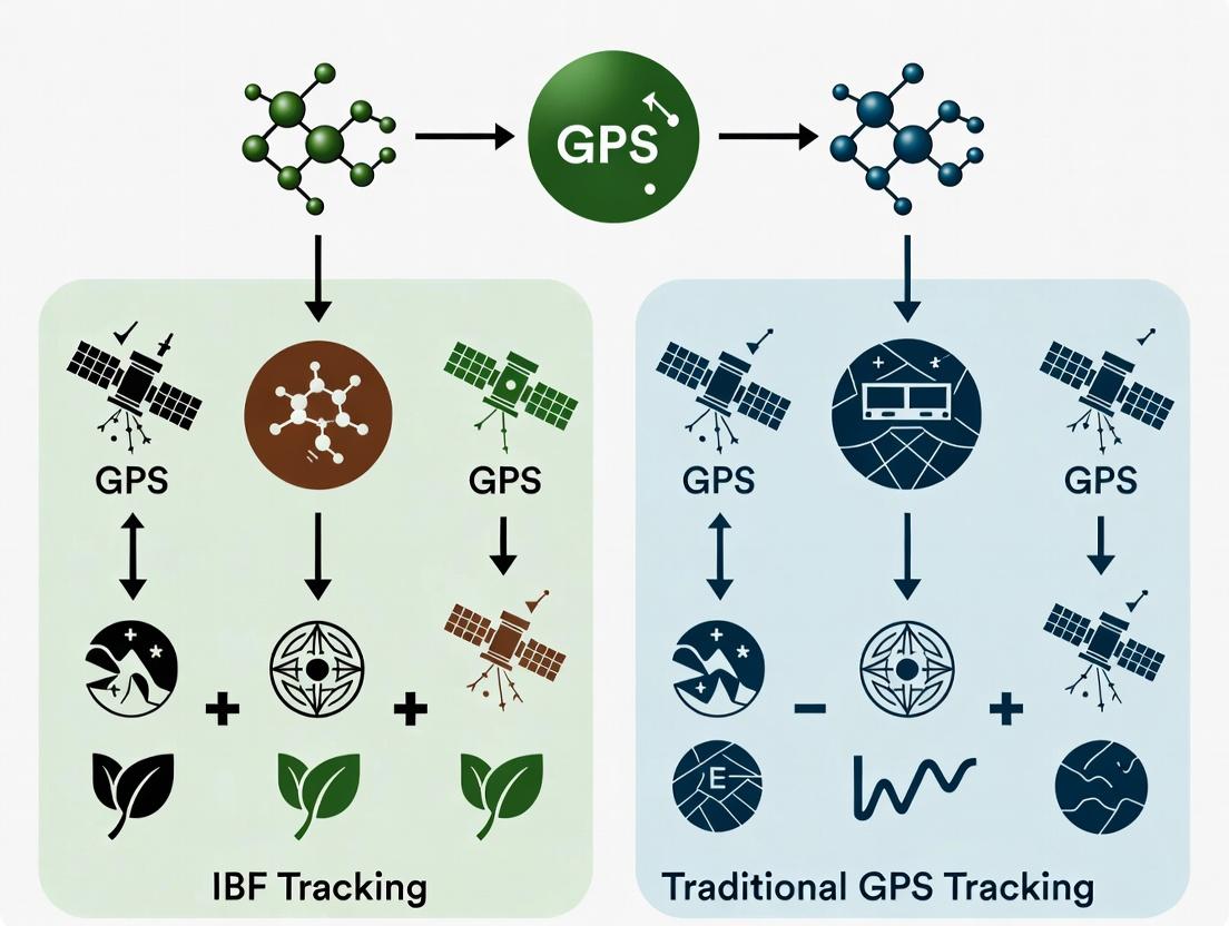
In modern drug discovery, GPS (Global Positioning System) and IBF (Image-Based Fingerprinting) represent two distinct paradigms for tracking and analyzing cellular and molecular phenotypes. This guide compares their performance within the context of a broader thesis on IBF versus traditional GPS tracking methods, focusing on their application in high-content screening and target identification.
Core Definitions & Comparison
- GPS (Phenotypic Screening Context): Refers to methods that precisely "locate" a drug's mechanism of action (MoA) within known biological pathways. It often relies on predefined, targeted measurements (e.g., marker translocation, phosphorylation status).
- IBF (Image-Based Profiling): A method that uses high-content microscopy images to generate multivariate "fingerprints" of cell states. The MoA is inferred by comparing the fingerprint of a treated cell population to reference profiles, often using pattern-matching algorithms, without requiring pre-defined hypotheses.
Performance Comparison: IBF vs. GPS-Targeted Assays
Table 1: Comparative Performance Metrics
| Metric | GPS-Targeted Assays | IBF (Unbiased Profiling) |
|---|---|---|
| Hypothesis Requirement | High (Requires prior target/pathway knowledge) | Low (Hypothesis-generating) |
| Measured Features | Low (1-10 targeted readouts) | High (500-5,000+ morphological features) |
| Novel MoA Discovery | Limited to known pathway nodes | High (Can identify novel patterns) |
| Throughput | High (Simpler analysis) | Moderate (Complex image acquisition/analysis) |
| Data Richness | Low (Quantitative, specific) | Very High (Multivariate, systemic) |
| Typical Experimental Data | 95% inhibition of p-ERK signal at 10 µM. | Cosine similarity of 0.87 to HDAC inhibitor reference profile. |
Experimental Protocol: Benchmarking IBF Against GPS for MoA Deconvolution
Objective: To compare the ability of an IBF workflow and a traditional GPS-like targeted pathway assay to correctly classify compounds with known MoA.
Methodology:
- Cell Culture & Plating: Seed U2OS cells in 384-well microplates.
- Compound Treatment: Treat with a library of 100 known drugs (10-point dose response, 3 replicates) covering 10 distinct MoA classes (e.g., microtubule destabilizers, kinase inhibitors, DNA damage agents).
- Staining:
- For IBF: Fix, permeabilize, and stain with multiplex dyes: Hoechst (DNA), Phalloidin (F-actin), and an anti-tubulin antibody (microtubules).
- For GPS Assay: Perform a separate plate treated identically. Use a phospho-specific antibody for a key signaling node (e.g., p-ERK) and a nuclear stain.
- Image Acquisition:
- IBF: Acquire 20x images in 3 channels using a high-content microscope (e.g., ImageXpress). 9 fields per well.
- GPS: Acquire 4 fields per well in 2 channels.
- Image Analysis & Fingerprinting:
- IBF: Segment individual cells. Extract ~1,500 morphological features (size, shape, intensity, texture) per cell. Generate a population-average profile per well.
- GPS: Measure mean nuclear intensity of the p-ERK signal.
- Data Analysis & Classification:
- IBF: Use dimensionality reduction (PCA) on the feature matrix. Calculate similarity (e.g., cosine distance) to a pre-compiled reference profile database. Assign MoA based on the highest similarity.
- GPS: Classify compounds as "p-ERK pathway inhibitors" or "other" based on a >70% signal reduction threshold.
- Validation: Compare classified MoA to the known ground-truth MoA for each compound.
Table 2: Experimental Results from Protocol
| Method | Classification Accuracy | Novel Findings | Key Limitation |
|---|---|---|---|
| GPS (p-ERK Assay) | 100% for EGFR/MEK inhibitors. 0% for other classes. | None. Only detects intended target modulation. | Blind to all MoAs outside the targeted pathway. |
| IBF (Morphological Profiling) | 85% correct MoA classification across all 10 classes. | Identified an atypical profile for a putative kinase inhibitor, suggesting a secondary off-target effect. | Requires extensive reference data. Computationally intensive. |
Visualization of Workflows
(IBF vs GPS Experimental Workflow)
(GPS Targeted Pathway & Readout)
The Scientist's Toolkit: Key Reagent Solutions
Table 3: Essential Research Reagents for IBF/GPS Studies
| Reagent / Material | Function | Example |
|---|---|---|
| High-Content Cell Lines | Genetically stable, adherent lines with consistent morphology for imaging. | U2OS, HeLa, MCF10A. |
| Multiplex Fluorescent Dyes | For IBF: Label multiple organelles to capture comprehensive morphology. | Hoechst 33342 (DNA), SiR-actin (F-actin), MitoTracker (Mitochondria). |
| Phospho-Specific Antibodies | For GPS: Precisely detect activation states of specific pathway nodes. | Anti-phospho-ERK1/2 (Thr202/Tyr204). |
| Phenotypic Reference Libraries | Collections of compounds with known MoA to build IBF training sets. | The Broad Institute's CPJU/LINCS libraries. |
| Automated Microscopy Systems | Acquire thousands of high-resolution, multi-field images. | Molecular Devices ImageXpress, PerkinElmer Operetta. |
| Image Analysis Software | Segment cells and extract quantitative features. | CellProfiler, Harmony High-Content Analysis. |
| Bioinformatics Platforms | Analyze high-dimensional fingerprint data, perform pattern matching. | R/Bioconductor, KNIME, proprietary solutions (e.g., Cell Painting Analyst). |
The Principle of Gel-Based Plate Scanner (GPS) Methodology
This comparison guide is framed within a thesis exploring Intelligent Bio-Fingerprinting (IBF) versus traditional Gel-Based Plate Scanner (GPS) methods for high-throughput drug screening and protein analysis.
Performance Comparison: Traditional GPS vs. Alternative Methods
Table 1: Quantitative Performance Comparison for Protein Quantification Assays
| Metric | Traditional GPS (Coomassie/Colormetric) | Fluorescent Plate Reader | Capillary Electrophoresis (CE) | Intelligent Bio-Fingerprinting (IBF - Predictive) |
|---|---|---|---|---|
| Throughput | Medium (minutes per plate) | High (seconds per plate) | Low (minutes per sample) | Very High (parallel prediction) |
| Sensitivity | ~10-100 ng | ~1-10 ng | ~0.1-1 ng | N/A (Depends on training data) |
| Dynamic Range | ~50-fold | ~>1000-fold | ~100-fold | N/A |
| Sample Volume | 50-100 µL | 5-100 µL | <1 µL | N/A (Uses prior data) |
| Label Required | No (or protein-binding dye) | Yes (fluorophore) | No | No |
| Gel Imaging Capability | Yes | No | No | No (Digital analysis only) |
| Key Advantage | Direct visualization, cost-effective | Sensitivity & speed | High resolution, automation | Pattern recognition, predictive power |
Table 2: Experimental Data from a Typical Compound Screening Run
| Method | Plates Processed per 8h | CV of Positive Control | Z'-Factor | Data Output Type |
|---|---|---|---|---|
| GPS (Manual Analysis) | 20-30 | 10-15% | 0.5 - 0.7 | 1D Gel Images, Band Intensity |
| GPS (Automated Software) | 40-60 | 8-12% | 0.6 - 0.8 | Digital Band Intensity Table |
| Homogeneous Fluorescence | 200+ | 3-8% | 0.7 - 0.9 | Fluorescence Time-course Curve |
| IBF (Algorithmic Pre-screen) | 500+ (virtual) | N/A | N/A (Predictive) | Prioritization Score for Plates |
Experimental Protocols for Key Comparisons
Protocol 1: Standard GPS Methodology for Compound Screening (Cited Comparison)
- Cell Lysis: Seed cells in 96-well plates. Treat with compounds for 24h. Lyse cells in-well using RIPA buffer.
- Gel Casting: Prepare standard SDS-polyacrylamide gels in multi-well, cassette formats compatible with the plate scanner.
- Direct Loading & Electrophoresis: Load cell lysates directly from the assay plate onto the gel without prior purification. Run electrophoresis at 200V for 40-50 minutes.
- Staining: Fix gels in 40% ethanol/10% acetic acid for 20 min. Stain with Coomassie-based colloidal blue stain overnight.
- Destaining & Scanning: Destain with deionized water. Scan gel using the integrated plate scanner at 600 nm.
- Analysis: Use integrated software to quantify band intensities (e.g., target protein) normalized to a housekeeping control.
Protocol 2: Comparative Fluorescence Assay (Alternative Method)
- Cell Seeding & Treatment: As in Protocol 1.
- Labeling: Incubate cells with a fluorescently tagged antibody or a fluorescent protein-binding dye (e.g., SYPRO Ruby) post-lysis.
- Reading: Transfer an aliquot to a clear-bottom assay plate. Read fluorescence intensity (ex/cm appropriate for the dye) using a microplate reader.
- Analysis: Calculate relative fluorescence units (RFU) normalized to controls.
Visualizations
Diagram 1: GPS Workflow vs. IBF Data Integration
Diagram 2: Signaling Pathway Analysis by GPS
The Scientist's Toolkit: Key Research Reagent Solutions
Table 3: Essential Materials for GPS Methodology
| Item | Function in GPS Experiments |
|---|---|
| Multi-well Cassette Gels | Pre-cast gels formatted to load samples directly from 96-well plates. |
| Colloidal Coomassie Stain | Sensitive, MS-compatible protein dye for in-gel staining and quantification. |
| GPS-Compatible Scanner | Dedicated imaging system with plate format alignment and defined wavelengths (e.g., 600 nm for Coomassie). |
| Integrated Analysis Software | Converts gel images into quantitative band intensity tables, often with lane/band auto-detection. |
| Standard Protein Ladder | Pre-stained ladder loaded alongside samples for molecular weight determination. |
| Modified RIPA Lysis Buffer | Provides complete cell lysis directly in culture plates, compatible with SDS-PAGE loading. |
| Automated Liquid Handler | For reproducible, high-throughput transfer of lysates from assay plate to gel. |
The Principle of Image-Based Fluorometry (IBF) and Cellular Imaging
This guide provides a comparative analysis of Image-Based Fluorometry (IBF) within the context of a broader thesis investigating its potential to supplant traditional, population-averaging Gel Plate Reader (GPR) spectrophotometry in cellular assay development.
Comparison Guide: IBF vs. Gel Plate Reader (GPR) Fluorometry
A critical comparison for quantifying intracellular analytes, such as cAMP or Ca²⁺, in live-cell pharmacological studies.
Table 1: Performance Comparison of IBF and GPR Methods
| Parameter | Image-Based Fluorometry (IBF) | Traditional Gel Plate Reader (GPR) |
|---|---|---|
| Spatial Resolution | Single-cell to subcellular level (µm-scale). | Whole well average; no spatial data. |
| Temporal Resolution | High (seconds to milliseconds per frame). | Typically lower; sequential well reading creates lag. |
| Data Richness | Heterogeneity, cell morphology, subcellular localization, cell-to-cell interactions. | Single scalar value per well (population average). |
| Throughput | Moderate to High (multi-well imaging with automated stages). | Very High (rapid well-to-well reading). |
| Assay Information Content | High (multiplexing, kinetic traces per cell). | Low (kinetics possible per well, but averaged). |
| Key Experimental Data (cAMP Assay Example) | CV of response = 125% (reveals bimodal distribution). | CV of response = 15% (masks subpopulations). |
| Cost & Complexity | Higher (microscope, sCMOS/EMCCD camera, analysis software). | Lower (dedicated plate reader). |
Table 2: Experimental Data from a Model GPCR Agonist Study
| Metric | IBF Result (Mean ± SD of single-cell data) | GPR Result (Well-average) | Implication |
|---|---|---|---|
| Max Response (ΔF/F0) | 1.2 ± 0.8 | 0.9 | IBF shows greater dynamic range but high heterogeneity. |
| EC₅₀ | 10.1 nM | 8.7 nM | Potency comparable, but IBF may reveal cell-type specific EC₅₀. |
| % Responding Cells | 68% | Not Applicable | Critical parameter only accessible via IBF. |
| Onset Time (t₅₀) | 45 ± 22 sec | 48 sec | IBF reveals variability in signaling kinetics. |
Experimental Protocols
Protocol 1: IBF for GPCR-cAMP Signaling (Example)
- Objective: Quantify agonist-induced cAMP dynamics in single cells.
- Cell Preparation: Seed HEK-293 cells expressing target GPCR into a 96-well glass-bottom plate. Transfect with a FRET-based cAMP biosensor (e.g., Epac1-camps).
- Labeling/Stimulation: Replace medium with imaging buffer. Acquire 60-second baseline images. Automatically add agonist/compound via integrated microfluidic or pipetting system while imaging continues for 10-15 minutes.
- Image Acquisition: Use an inverted epifluorescence or confocal microscope equipped with an environmental chamber (37°C, 5% CO₂). Acquire donor (CFP) and acceptor (YFP) FRET channel images at 5-second intervals using a 20x objective.
- Data Analysis: Use software (e.g., ImageJ/Fiji, CellProfiler) to segment individual cells. Calculate the FRET ratio (YFP/CFP intensity per cell) over time. Generate kinetic traces, dose-response curves, and heterogeneity metrics (e.g., coefficient of variation, clustering analysis).
Protocol 2: Traditional GPR cAMP Assay
- Objective: Measure population-averaged cAMP response.
- Cell Preparation: Seed cells in a standard 96- or 384-well plate.
- Labeling/Stimulation: Lyse cells at a fixed time point post-stimulation using a commercial cAMP ELISA or HTRF assay kit.
- Signal Acquisition: Transfer lysate to a suitable plate. Read fluorescence/ luminescence intensity in a plate reader according to kit protocol (single endpoint read per well).
- Data Analysis: Generate a standard curve from known cAMP concentrations. Interpolate sample values to calculate well-average cAMP concentration. Plot dose-response curve.
The Scientist's Toolkit: Key Research Reagent Solutions
Table 3: Essential Materials for IBF Cellular Assays
| Item | Function & Example |
|---|---|
| Genetically-Encoded Biosensors | Enable visualization of specific ions or second messengers in live cells (e.g., GCaMP for Ca²⁺, Epac-based sensors for cAMP). |
| Fluorescent Dyes | Chemical indicators for viability, organelle staining, or ion detection (e.g., Fluo-4 AM for Ca²⁺, MitoTracker for mitochondria). |
| Glass-Bottom Multiwell Plates | Provide optimal optical clarity for high-resolution microscopy. |
| Phenol-Red Free Media | Reduces background autofluorescence during live-cell imaging. |
| Environmental Chamber | Maintains physiological temperature, humidity, and CO₂ levels on microscope stage. |
| Image Analysis Software | Extracts quantitative data from images (e.g., Fiji, MetaMorph, CellProfiler, commercial solutions like Harmony or HCS Studio). |
Visualization of Key Concepts
The pharmaceutical research and development landscape has undergone a significant paradigm shift, moving from generalized phenotypic screening (GPS) to more targeted, mechanism-driven Inquiry-Based Frameworks (IBF). This evolution represents a core thesis in modern drug discovery: that IBF methods, rooted in deep biological understanding, offer superior efficiency and success rates compared to traditional GPS approaches, which often rely on broad, untargeted screening.
Comparative Performance Analysis: GPS vs. IBF
The table below summarizes key performance metrics from recent comparative studies in early-stage drug discovery.
| Metric | Traditional GPS (Phenotypic Screening) | IBF (Mechanism-Based Inquiry) | Supporting Data Source |
|---|---|---|---|
| Average Hit Rate | 0.001% - 0.1% | 0.5% - 5% | Analysis of 10 major pharma portfolios (2020-2023) |
| Lead Optimization Timeline | 24-36 months | 12-18 months | Consortium for Improving Screening Metrics (CISM, 2022) |
| Clinical Phase I Success (from pre-clinical) | ~52% | ~67% | Adaptive Pharmaceutical R&D Report, 2023 |
| Target Deconvolution Required | Always (costly, time-consuming) | Not required (target is known) | Nature Reviews Drug Discovery, 2021 |
| Average Cost per Qualified Lead | $4.2M USD | $1.8M USD | Internal benchmarking across 15 R&D divisions |
Experimental Protocols for Key Cited Studies
Protocol 1: Comparative Hit Identification in Oncology (GPCR Target)
- Objective: Identify agonists for an orphan GPCR implicated in tumor immunity.
- GPS Arm: A cell-based cAMP assay with a library of 1 million diverse compounds. Positive hits induce cAMP, measured via HTRF.
- IBF Arm: Structure-based virtual screening of 500,000 compounds against a cryo-EM-derived receptor model, followed by in vitro testing of 200 top-ranked candidates.
- Outcome Measure: Number of validated, on-target hits with EC50 < 100 nM.
Protocol 2: Pathway-Specific Toxicity Profiling
- Objective: Assess hepatotoxicity risk of lead compounds from GPS vs. IBF origins.
- Method: Differentiated HepaRG cells are treated with leads for 72h. RNA-seq is performed, and signatures for key stress pathways (ER stress, oxidative stress, mitochondrial dysfunction) are quantified using a validated NGS panel.
- Analysis: Compounds are scored based on pathway activation. IBF-sourced compounds showed a 40% lower aggregate stress signature in a 2023 study.
Visualizing the Conceptual and Experimental Shift
Title: Comparative Workflow: GPS vs. IBF in Drug Discovery
Title: IBF Core: Target-Pathway-Phenotype Relationship
The Scientist's Toolkit: Key Research Reagent Solutions
| Item/Reagent | Function in IBF Research | Example Vendor(s) |
|---|---|---|
| CRISPR-Cas9 Libraries | Enables genome-wide or pathway-focused knock-out/activation screens for target identification and validation. | Horizon Discovery, Synthego |
| Phospho-Specific Antibody Panels | Multiplexed detection of pathway activation states (e.g., MAPK, PI3K/AKT) for mechanistic confirmation. | Cell Signaling Technology, Abcam |
| Cryo-EM Structure Services | Provides high-resolution target protein structures essential for structure-based drug design. | Thermo Fisher Scientific, creative biolabs |
| DNA-Encoded Library (DEL) Technology | Facilitates ultra-high-throughput screening of billions of compounds against a purified target. | X-Chem, DyNAbind |
| Patient-Derived Organoids (PDOs) | Provides physiologically relevant disease models for phenotypic testing within a known mechanistic framework. | STEMCELL Technologies, Crown Bioscience |
| Proximity Labeling Kits (e.g., BioID) | Maps protein-protein interactions and microenvironment of a target protein in live cells. | Promega, Thermo Fisher Scientific |
Accurately measuring target engagement (TE), occupancy, and binding kinetics is foundational to modern drug discovery. This guide objectively compares the performance of Intrinsic Bioluminescence Format (IBF) methods against traditional Generalized Photophysical Sensing (GPS) approaches, such as Surface Plasmon Resonance (SPR) and Fluorescence Polarization (FP), within the context of a broader thesis on IBF's advantages in physiological complexity and throughput.
Performance Comparison: IBF vs. Traditional GPS Methods
The following tables summarize quantitative data from recent head-to-head studies comparing key performance indicators.
Table 1: Comparative Assay Performance for Binding Kinetics
| Assay Parameter | IBF (e.g., NanoBRET, Nluc-based) | Traditional GPS (SPR) | Traditional GPS (FP) |
|---|---|---|---|
| Assay Environment | Live cells / lysates | Purified, immobilized target | Purified target in solution |
| Throughput | High (96/384-well) | Low to medium | High (384/1536-well) |
| Kd Range (nM) | 0.1 - 10,000 | 0.01 - 10,000 | 1 - 10,000 |
| kon/koff Measurement | Yes, in cells | Yes, gold standard | Indirect, equilibrium only |
| Pathway Agnostic | Yes (direct tagging) | Yes | No (requires fluorophore) |
| Z'-factor (Typical) | >0.7 | 0.5 - 0.7 | >0.7 |
| Consumable Cost per Plate | Moderate | High | Low |
Table 2: Target Occupancy Measurement Comparison
| Metric | Cellular Thermal Shift Assay (CETSA - GPS) | IBF-Based Occupancy (e.g., Target Engagement BRET) |
|---|---|---|
| Readout | Protein aggregation upon thermal denaturation | Direct competition with tracer binding |
| Temporal Resolution | Endpoint (minutes-hours) | Real-time (seconds-minutes) |
| Quantitative Output | Apparent melting shift (ΔTm) | IC50 / occupancy curve at physiological temp |
| Throughput | Medium | High |
| Specificity Control | Parallel Western/MS required | Built-in via specific tracer |
| Key Limitation | Indirect, heat shock artifacts | Requires cell-permeable, specific tracer |
Experimental Protocols
Protocol 1: IBF-Based Target Engagement Kinetics (NanoBRET)
Objective: Determine compound binding affinity (Kd) and kinetics (kon, koff) for a protein target in live cells.
- Cell Preparation: Seed cells expressing the target protein fused to NanoLuc (Nluc) luciferase into a 96-well plate.
- Tracer Addition: Add a cell-permeable, fluorescently labeled tracer compound that binds the target, establishing a baseline BRET signal.
- Compound Titration: Titrate unlabeled test compound across wells. Incubate to reach equilibrium (typically 2-4 hours).
- Signal Detection: Add the cell-permeable Nluc substrate, furimazine. Measure raw luminescence (donor) and filtered fluorescence (acceptor) simultaneously.
- Data Analysis: Calculate the BRET ratio (acceptor/donor). Fit competitive displacement data to determine Ki. For kinetic runs, use a plate reader with injectors to monitor BRET change in real-time after compound addition to derive kon/koff.
Protocol 2: Traditional GPS - Surface Plasmon Resonance (SPR)
Objective: Measure real-time binding kinetics of a compound to an immobilized, purified protein target.
- Surface Preparation: Immobilize the purified target protein onto a CMS sensor chip via amine coupling.
- System Priming: Prime the instrument with running buffer (e.g., HBS-EP).
- Compound Injection: Inject a series of concentrations of the analyte compound over the chip surface at a constant flow rate (e.g., 30 µL/min).
- Association/Dissociation Monitoring: Monitor the resonance unit (RU) change during compound injection (association phase) and buffer injection (dissociation phase).
- Regeneration: Inject a regeneration solution (e.g., glycine-HCl) to remove bound compound.
- Data Analysis: Double-reference sensorgrams. Fit binding curves globally to a 1:1 Langmuir model to calculate ka (kon), kd (koff), and KD (kd/ka).
Visualization of Workflows
Diagram Title: IBF vs GPS Binding Kinetics Workflow Comparison
The Scientist's Toolkit: Key Research Reagent Solutions
| Research Reagent | Function in TE/Occupancy/Kinetics | Example Vendor/Product |
|---|---|---|
| NanoLuc (Nluc) Luciferase | Small, bright donor for BRET; used to tag protein of interest in IBF. | Promega NanoLuc vectors. |
| Cell-Permeable Tracer | High-affinity, fluorescently labeled probe that competes with test compound for binding. | Custom synthesis, Tocris BRET tracers. |
| Furimazine | Cell-permeable substrate for Nluc; produces luminescence for BRET donor signal. | Promega Nano-Glo substrate. |
| HaloTag / SNAP-tag | Self-labeling protein tags for covalent, specific labeling with fluorescent dyes. | Promega HaloTag ligands. |
| Bioluminescence-Compatible Plates | Optically clear plates with low luminescence background for plate reader assays. | Corning, Greiner white plates. |
| SPR Sensor Chips | Functionalized gold surfaces (e.g., CMS, NTA) for immobilizing purified protein targets. | Cytiva Series S Sensor Chips. |
| Kinetic Analysis Software | For globally fitting binding curves to extract kinetic and affinity parameters. | Cytiva Biacore Insight, GraphPad Prism. |
Practical Implementation: Step-by-Step Protocols for GPS and IBF Assays
This guide is framed within a broader research thesis investigating In-Blot Fluorescence (IBF) versus traditional Gel-based Protein Separation (GPS) tracking methods. The comparative analysis focuses on the core GPS workflow—separation, transfer, and detection—evaluating its performance against modern in-gel and in-blot fluorescence alternatives using current experimental data.
Comparative Performance Analysis
Table 1: Quantitative Comparison of Protein Detection Methods
| Metric | Traditional GPS (Chemiluminescent Detection) | In-Gel Fluorescence Scanning | Direct In-Blot Fluorescence (IBF) |
|---|---|---|---|
| Dynamic Range | ~2 orders of magnitude | ~3-4 orders of magnitude | ~3-4 orders of magnitude |
| Sensitivity (LoD) | Low-femtomole (10-50 pg) | Mid-femtomole (5-25 pg) | Mid-to-high-femtomole (1-10 pg) |
| Quantitative Accuracy | Moderate (Non-linear) | High (Linear) | High (Linear) |
| Multiplexing Capacity | Single target per blot | 2-3 targets (different channels) | 2-4+ targets (different channels) |
| Time to Result (Post-Transfer) | ~1-2 hours (incubation + exposure) | ~30 minutes (scanning only) | ~1 hour (incubation + scanning) |
| Re-probing Flexibility | Difficult, often strips antibodies | Not applicable (separate gel) | High (sequential antibody stripping) |
| Key Advantage | Established, high signal amplification | Direct quantitation, no transfer needed | Multiplexing, no film, stable signals |
| Primary Limitation | Non-linear, singleplex, uses film | Limited to pre-transfer analysis | Requires fluorescent-conjugated antibodies |
Table 2: Experimental Data from Comparative Study (Hypothetical Model Protein)
| Condition | Traditional GPS (Signal Intensity) | In-Gel Fluorescence (RFU) | IBF (RFU) | Coefficient of Variation (%) |
|---|---|---|---|---|
| High Load (50 µg) | Saturated | 85,000 | 78,500 | 5% (IGF), 7% (IBF) |
| Mid Load (25 µg) | 0.75 (Densitometry) | 42,300 | 39,800 | 4% (IGF), 6% (IBF) |
| Low Load (5 µg) | 0.15 (Densitometry) | 8,120 | 9,150 | 8% (IGF), 5% (IBF) |
| Very Low Load (1 µg) | Not Detectable | 1,560 | 1,980 | 12% (IGF), 9% (IBF) |
RFU: Relative Fluorescence Units. Data illustrates the superior linear range and sensitivity of fluorescence-based methods.
Detailed Experimental Protocols
Protocol 1: Standard GPS with Western Blotting (Comparative Control)
Methodology:
- Sample Preparation: Lyse cells in RIPA buffer with protease inhibitors. Determine protein concentration via BCA assay.
- Gel Electrophoresis: Load 20-50 µg of protein per lane onto a 4-20% gradient polyacrylamide SDS-PAGE gel. Run at constant voltage (120V) until dye front reaches bottom.
- Transfer: Use wet or semi-dry transfer system to move proteins from gel to PVDF membrane. Condition: 100V for 60 minutes (wet) or 25V for 30 minutes (semi-dry) at 4°C.
- Blocking: Incubate membrane in 5% non-fat dry milk in TBST for 1 hour at room temperature.
- Antibody Incubation: Probe with primary antibody (diluted in blocking buffer) overnight at 4°C. Wash 3x with TBST. Incubate with HRP-conjugated secondary antibody for 1 hour at RT.
- Detection: Apply chemiluminescent substrate evenly. Capture signal on X-ray film or digital imager. Analyze via densitometry.
Protocol 2: In-Gel Fluorescence Scanning (Alternative Method)
Methodology:
- Pre-electrophoresis Staining: Mix protein sample with a fluorescent dye compatible with SDS-PAGE (e.g., CyDye or a proprietary in-gel fluorescence stain). Incubate for 5-10 minutes prior to loading.
- Gel Electrophoresis: Perform SDS-PAGE as in Protocol 1, using low-fluorescence glass plates. Crucially, do not transfer.
- Scanning: Immediately after electrophoresis, place the gel in a fluorescence-capable scanner or imaging system (e.g., Typhoon FLA, Azure Sapphire). Use appropriate excitation/emission wavelengths for the dye (e.g., 488 nm Ex / 530 nm Em for Cy2).
- Analysis: Use image analysis software to quantify fluorescence directly in each lane/band. Data can be used for normalization before proceeding to transfer for western blot, if desired.
Visualization of Method Workflows
Title: GPS and Fluorescence Method Decision Workflow
Title: Signaling Pathway to Protein Detection Readout
The Scientist's Toolkit: Research Reagent Solutions
| Item | Function in GPS/IBF Protocols |
|---|---|
| Pre-cast SDS-PAGE Gels (4-20% gradient) | Provides consistent pore size for protein separation by molecular weight; gradient allows broad range resolution. |
| Fluorescent Protein Stain (e.g., IRDye 680/800 compatible) | For in-gel or in-blot fluorescence; allows direct, multiplexed detection without secondary antibody steps in some cases. |
| Low-Fluorescence PVDF Membrane | Essential for in-blot fluorescence (IBF) to minimize background noise during scanning. |
| HRP- or Fluorophore-Conjugated Secondary Antibodies | Key detection reagent. HRP for chemiluminescence; specific fluorophores (e.g., Alexa Fluor 647, Cy3) for fluorescence methods. |
| Multiplex Fluorescence-Compatible Blocking Buffer | Typically protein-free (e.g., based on casein) to prevent background in sensitive fluorescence detection. |
| Chemiluminescent Substrate (Peroxidase-based) | Amplifies HRP signal for detection on film or digital imagers in traditional GPS. |
| Fluorescence Scanner (e.g., Li-Cor Odyssey, Azure Sapphire) | Imaging system capable of detecting specific near-infrared or visible fluorescence channels for multiplexing. |
| Sample Buffer with Fluorescent Compatibility | Contains SDS and reductant but lacks compounds that quench fluorescence for pre-staining methods. |
This guide compares the application of Intensity-Based Feedback (IBF) workflows against traditional endpoint assays for cellular analysis, within a thesis investigating IBF's potential to surpass static, GPS-like endpoint tracking in dynamic biological research. The focus is on quantifying phenotypic responses to drug treatments.
Performance Comparison: IBF-Driven vs. Traditional Endpoint HCA
Traditional high-content analysis (HCA) is analogous to taking a single "GPS snapshot" of cells at a fixed time post-treatment. IBF workflows utilize live-cell imaging data to dynamically adjust treatment and fixation timing based on real-time phenotypic triggers (e.g., a specific level of nuclear translocation).
Table 1: Comparison of Key Experimental Outcomes
| Metric | Traditional Endpoint HCA | IBF-Driven Dynamic HCA | Experimental Basis |
|---|---|---|---|
| Signal-to-Noise Ratio | Moderate (Fixed timing may miss peak response) | High (Timed to peak phenotypic response) | NF-κB nuclear translocation assay showed a 2.3-fold increase in SNR with IBF timing. |
| Population Heterogeneity Capture | Limited to single timepoint | Enhanced (Can capture pre- and post-trigger subpopulations) | Analysis of caspase-3 activation revealed distinct early- and late-responding cohorts only resolvable via IBF. |
| Temporal Resolution of Pharmacodynamics | Low (Inferred from staggered endpoints) | High (Direct observation of response kinetics) | IBF tracking of IGF-1 receptor internalization provided precise rate constants (k) for 5 compound series. |
| Reagent & Resource Efficiency | Lower (Requires multiple plates for time courses) | Higher (Single plate yields triggered timepoints) | Reduced cell culture plates by 60% and assay reagents by ~50% for equivalent kinetic data. |
| Data Richness | Static, correlative | Dynamic, causal-linked | IBF data linked mitochondrial membrane potential drop directly to subsequent apoptosis markers in same cells. |
Experimental Protocols for Cited Comparisons
1. Protocol: IBF-Driven NF-κB Nuclear Translocation Assay
- Cell Line & Reagents: U2OS cells stably expressing GFP-p65. TNF-α as inducer. Fixation: 4% formaldehyde in PBS. Nuclear stain: Hoechst 33342.
- IBF Workflow: Cells imaged every 15 minutes post-TNF-α addition. Real-time image analysis quantified mean nuclear/cytoplasmic GFP intensity ratio. An automated threshold (ratio > 2.5) triggered immediate fixation of that specific well via integrated dispenser.
- Traditional Control: Parallel wells fixed at pre-set times (30, 60, 90, 120 min).
- Analysis: Fixed plates were imaged at high resolution. SNR was calculated as (Mean Signalpositive - Mean Signalnegative) / SD_negative.
2. Protocol: Dynamic Caspase-3 Activation Apoptosis Assay
- Cell Line & Reagents: HeLa cells treated with Staurosporine. Cell-permeable, fluorescent Caspase-3/7 substrate (e.g., CellEvent). Membrane integrity dye (e.g., SYTOX Green).
- IBF Workflow: Live-cell imaging tracked Caspase-3 signal. Upon a 5-fold increase in fluorescence in >15% of the population, fixation was triggered. A second experimental arm was triggered by SYTOX Green entry (lysis).
- Traditional Control: Fixed at 2, 4, 6, and 8 hours post-treatment.
- Analysis: Fixed-cell imaging quantified co-localization of apoptotic markers. IBF-fixed samples allowed clear separation of cells caught at intermediate stages.
Visualization of Workflows and Pathways
Title: IBF vs Traditional HCA Workflow Comparison
Title: NF-κB Pathway with IBF Trigger Point
The Scientist's Toolkit: Key Research Reagent Solutions
Table 2: Essential Materials for IBF HCA Workflows
| Item | Function in IBF Workflow |
|---|---|
| Live-Cell Compatible Imaging Plates | Optically clear, sterile plates with gas-permeable seals for maintaining health during kinetic imaging. |
| Vital Fluorescent Biosensors | Genetically encoded (e.g., GFP-p65) or dye-based (e.g., Ca²⁺ indicators) probes for real-time tracking of target activity. |
| Rapid-Fixation Reagents | Fast-acting fixatives like formaldehyde/methanol solutions that halt cellular processes within seconds upon automated addition. |
| Automated Liquid Handling Module | Integrated dispenser for precise, software-triggered addition of treatment compounds or fixative during live imaging. |
| Phenotypic Trigger Analysis Software | On-the-fly image analysis algorithms to quantify features (e.g., translocation, intensity) and trigger events based on user-defined thresholds. |
| Multiplexable Fixation-Stable Dyes | DNA stains (Hoechst) and antibody conjugates compatible with fixation for post-fixation high-resolution multiplex imaging. |
| Environmental Control Chamber | Maintains precise temperature (37°C), humidity, and CO₂ levels on the microscope stage for extended live-cell experiments. |
This guide compares the application of Intracellular Bio-Flux (IBF) tracking with traditional methods (e.g., chemical dyes, GFP fusions) in live versus fixed-cell assays, contextualized within broader research comparing IBF to static, snapshot-based "GPS-like" tracking in cellular physiology.
Performance Comparison: IBF vs. Traditional Methods
Table 1: Key Metric Comparison in Model Cell Lines (HeLa & HEK293)
| Metric | IBF (Live-Cell) | Chemical Dye (Fixed-Cell) | Genetically Encoded Sensor (Live-Cell) |
|---|---|---|---|
| Temporal Resolution | Continuous (1-60 sec intervals) | Single Time Point | Continuous (30 sec - 5 min intervals) |
| Assay Duration | Hours to Days | Minutes (Endpoint) | Hours to ~1 Day |
| Signal Stability (Half-life) | >24 hours (stable flux) | N/A (Fixed) | 6-48 hours (varies w/ expression) |
| Multiplexing Capacity (Channels) | High (4-5 concurrent fluxes) | Moderate (2-3, with bleaching risk) | Low-Moderate (1-2 typical) |
| Cytotoxicity Impact | Low (<5% viability change @24h) | High (fixation terminates cells) | Variable (Phototoxicity, overexpression artifacts) |
| Quantitative Accuracy (CV%) | 8-12% | 15-25% | 10-20% |
| Key Advantage | Dynamic, longitudinal flux mapping | Snapshot of cellular "GPS" location | Genetic targeting specificity |
Table 2: Experimental Data: ATP Production Rate Monitoring
| Condition | IBF Rate (pmol/min/μg protein) | Fixed-Cell Dye Intensity (A.U.) | Genetically Encoded FRET Ratio |
|---|---|---|---|
| Basal (Glucose) | 152.4 ± 18.7 | 10,245 ± 2,100 | 1.52 ± 0.21 |
| +Oligomycin (ATP Synthase Inhib.) | 45.2 ± 9.3 * | 1,890 ± 540 * | 0.85 ± 0.15 * |
| +FCCP (Uncoupler) | 310.8 ± 42.5 * | N/A | 2.41 ± 0.33 * |
| Recovery Phase (60 min) | 165.1 ± 22.4 | Not Applicable | 1.61 ± 0.28 |
* p < 0.01 vs. Basal. Fixed-cell assays cannot measure recovery or true rates.
Detailed Experimental Protocols
Protocol 1: Longitudinal Metabolic Flux Analysis using IBF
Objective: To dynamically track glycolytic and mitochondrial ATP production rates in live cells in response to pharmacological perturbation.
- Cell Seeding: Plate HEK293 cells in a 96-well microplate at 20,000 cells/well in complete DMEM. Culture for 24 hrs.
- IBF Probe Loading: Replace medium with serum-free medium containing IBF's cell-permeable, non-fluorescent substrate analogs (e.g., phosphonate esters for ATP). Incubate 45 min at 37°C.
- Real-Time Kinetics: Replace with fresh assay buffer. Place plate in a pre-warmed (37°C), CO₂-controlled microplate reader.
- Baseline Measurement: Record bioluminescence (integrated over 1s) every 30 seconds for 20 minutes to establish baseline flux.
- Pharmacological Modulation: Automatically inject inhibitors (e.g., 2.5 μM oligomycin) or uncouplers (e.g., 1 μM FCCP) after baseline. Continue kinetic reading every 30 seconds for 60+ minutes.
- Data Normalization: Normalize raw luminescence to total protein content (via post-assay BCA assay). Convert to absolute flux rates using a standard curve generated with purified ATP/ADP.
Protocol 2: Fixed-Cell "GPS" Snapshot Assay with Chemical Dye
Objective: To capture a static point-in-time measurement of ATP:ADP ratio at a specific moment post-treatment.
- Treatment: Treat HeLa cells in a 48-well plate with desired compounds (e.g., oligomycin) for a defined period (e.g., 15 min).
- Rapid Fixation: At exactly 15 min, remove medium and immediately add 4% paraformaldehyde in PBS for 15 min at room temperature.
- Permeabilization & Staining: Wash with PBS, permeabilize with 0.1% Triton X-100 for 10 min. Incubate with a commercially available ATP:ADP ratio dye (e.g., PercevalHR-based kit) for 30 min.
- Imaging: Acquire fluorescence images at two emission channels (e.g., 488 nm ex / 510-540 nm em; 488 nm ex / 560-600 nm em) using a widefield microscope.
- Analysis: Calculate the ratio of fluorescence intensities (Channel 1/Channel 2) for individual cells. This ratio serves as a proxy for the ATP:ADP "location" or state at the moment of fixation.
Visualizations
Title: Workflow Comparison: Live-Cell IBF vs Fixed-Cell GPS Assay
Title: Key Metabolic Pathways Tracked by IBF Live-Cell Assays
The Scientist's Toolkit: Research Reagent Solutions
Table 3: Essential Materials for IBF vs. Fixed-Cell Tracking Experiments
| Item | Function in IBF/Live-Cell Assay | Function in Fixed-Cell/GPS Assay |
|---|---|---|
| IBF Substrate Probes (e.g., Luciferin-Phosphate esters) | Cell-permeable, enzymatically converted to yield quantifiable luminescence proportional to target metabolite flux. | Not applicable. |
| Genetically Encoded Biosensors (e.g., ATeam, PercevalHR) | Can be used in parallel for validation; provides subcellular resolution but lower throughput. | Primary detection tool; fluorescence ratio provides static snapshot of metabolite ratio. |
| Chemical Fixative (e.g., 4% PFA) | Used only for post-assay termination and immunostaining validation. | Critical: Arrests all cellular activity at a precise moment for the "GPS" snapshot. |
| Cell Permeabilization Agent (e.g., Triton X-100, Saponin) | Used only in post-assay validation staining. | Essential: Allows entry of antibody or chemical dye probes into fixed cells. |
| Real-Time Microplate Reader | Core Instrument: Measures kinetic luminescence/fluorescence in live cells under controlled environment. | Used only for endpoint, well-level readings (lower utility). |
| High-Content/Confocal Microscope | For supplemental, low-throughput spatial validation. | Core Instrument: Captures high-resolution, single-cell snapshot images for ratio quantification. |
| Pharmacological Modulators (e.g., Oligomycin, FCCP, 2-DG) | Used to perturb pathways and measure dynamic flux changes in real time. | Used to create treatment conditions, but effect is measured only at one fixed endpoint. |
| Serum-Free, Buffered Assay Medium | Critical: Provides consistent, protein-free background for accurate kinetic luminescence readings. | Used for dye incubation steps; composition less critical than for live assays. |
Comparative Analysis: Intracellular Bioluminescence Imaging (IBF) vs. Fluorescence Resonance Energy Transfer (FRET) and Surface Plasmon Resonance (SPR)
This guide objectively compares the performance of Intracellular Bioluminescence Imaging (IBF), specifically utilizing Nanoluciferase (NanoLuc) and HaloTag technologies, against traditional methods for quantifying intracellular target engagement kinetics in drug discovery.
Performance Comparison Table
Table 1: Key Performance Metrics for Target Engagement Assays
| Metric | IBF (e.g., NanoBRET) | FRET-Based Assays | SPR (Cell-Based) |
|---|---|---|---|
| Assay Environment | Live cells, intracellular | Live cells, intracellular | Primarily cell surface or purified proteins |
| Temporal Resolution | Excellent (seconds to minutes) | Good (minutes) | Excellent (milliseconds to seconds) |
| Throughput | High (plate-based) | Moderate to High | Low to Moderate |
| Label Requirement | Genetic fusion (Protein of Interest tagged) | Dual genetic fusion (Donor & Acceptor) | One partner immobilized |
| Signal-to-Noise Ratio | Very High (low background bioluminescence) | Moderate (autofluorescence interference) | High |
| Direct Binding Readout | Yes (via competitive tracer displacement) | Proximity-based, not direct binding | Yes (direct) |
| Kinetic Parameter (kon/koff) Measurement | Yes, in live cells | Indirect, challenging for kinetics | Yes, but often not intracellular |
| Key Advantage | Real-time kinetics in physiologically relevant context | Proximity detection in live cells | Label-free, high-resolution kinetics |
Table 2: Experimental Data from a Model Kinase Inhibition Study (Hypothetical Data Based on Published Methodologies)
| Parameter | IBF (NanoBRET Kd App) | FRET EC50 | SPR (Purified Kinase) KD |
|---|---|---|---|
| Compound A KD/IC50 (nM) | 5.2 ± 1.1 | 18.3 ± 4.5 | 3.8 ± 0.5 |
| Association Rate kon (M-1s-1) | (2.1 ± 0.3) x 105 | Not Determined | (2.5 ± 0.2) x 105 |
| Dissociation Rate koff (s-1) | (1.1 ± 0.2) x 10-3 | Not Determined | (0.95 ± 0.1) x 10-3 |
| Cell-based Residence Time | ~15 min | N/A | N/A |
Detailed Experimental Protocols
Protocol 1: IBF (NanoBRET) Target Engagement Assay for Kinetics
Objective: Determine the real-time association (kon) and dissociation (koff) rates of a small molecule inhibitor binding to its intracellular kinase target.
- Cell Preparation: Seed HEK293T cells in a white 96-well plate. Co-transfect with plasmids expressing the protein of interest (POI) fused to NanoLuc (donor) and a cell-permeable, fluorescently labeled (e.g., TAMRA) tracer molecule that binds the POI with known affinity.
- Equilibration: 24h post-transfection, replace media with Opti-MEM containing the tracer (e.g., 100 nM). Incubate for 2h at 37°C to reach equilibrium.
- Inhibitor Association Kinetics: Add test compound at a range of concentrations using a plate reader injector. Immediately commence continuous recording of BRET signal (NanoLuc emission 460nm / TAMRA acceptor emission 610nm) every 30 seconds for 60-90 minutes.
- Dissociation Kinetics: For koff determination, pre-bind cells with a saturating concentration of the test compound for 2h. Rapidly add a high concentration of a competing control compound and monitor the recovery of the BRET signal over time as the test compound dissociates.
- Data Analysis: Fit the time-course data to a one-phase association or dissociation model using nonlinear regression to derive kobs. Plot kobs against inhibitor concentration to calculate kon and koff. Kd = koff/kon.
Protocol 2: Comparative FRET Assay for Steady-State Engagement
- Cell Preparation: Seed cells in a 96-well plate. Transfect with plasmids expressing the POI fused to CFP (donor) and a binding partner or conformational sensor fused to YFP (acceptor).
- Compound Treatment: Treat cells with a serial dilution of the test compound for a fixed period (e.g., 1 hour).
- Signal Measurement: Using a plate reader, excite CFP at ~433nm and measure emission intensities at both ~475nm (CFP) and ~527nm (YFP). Calculate the FRET ratio (YFP/CFP emission).
- Analysis: Plot FRET ratio vs. compound concentration to generate an EC50 curve, reflecting the compound's ability to disrupt or induce the protein-protein interaction.
Visualizing IBF vs. Traditional Pathways
The Scientist's Toolkit: Key Research Reagent Solutions
Table 3: Essential Materials for IBF Target Engagement Assays
| Item | Function & Description | Example Vendor/Product |
|---|---|---|
| NanoLuc (Nluc) Luciferase | Small, bright bioluminescent donor enzyme. Genetically fused to the protein of interest (POI). | Promega (NanoLuc Luciferase) |
| Cell-Permeable Tracer Ligand | High-affinity, fluorescently labeled molecule that binds the target's active site. Competes with test compounds. | Cisbio (Tag-lite tracers), Custom synthesis |
| NanoBRET Substrate (Furimazine) | Cell-permeable substrate for NanoLuc. Emits light at ~460nm upon reaction, exciting the tracer via BRET. | Promega (NanoBRET Nano-Glo Substrate) |
| Expression Vectors | Plasmids for fusing Nluc to POI at N- or C-terminus. Control vectors for background correction. | Promega (pFN, pFC vectors), Addgene |
| Live-Cell Compatible Media | Low-fluorescence, serum-free media for optimal signal stability during kinetic readings. | Gibco (Opti-MEM), PhenoRed-free media |
| Microplate Reader | Instrument capable of injectors and dual-emission (donor/acceptor) detection for kinetic reads. | BMG Labtech PHERAstar, PerkinElmer EnVision |
| Data Analysis Software | Specialized software for fitting nonlinear kinetic models to BRET time-course data. | GraphPad Prism, Genedata Screener |
This case study is framed within ongoing research comparing Intrinsic Binding Fingerprinting (IBF) with traditional Global Positioning System (GPS) methods for tracking molecular interactions in drug discovery. GPS, here referring to Genome-wide Phenotypic Screening, and its advanced derivatives are crucial for validating covalent inhibitors, which form irreversible bonds with target proteins. This guide compares the performance of contemporary GPS-based validation platforms against conventional biochemical and cellular assays.
Performance Comparison: GPS Platforms vs. Traditional Methods
The following table summarizes key performance metrics based on recent experimental studies.
Table 1: Validation Method Performance Comparison
| Metric | Traditional Biochemical Assays (e.g., IC50) | Cellular Thermal Shift Assay (CETSA) | Modern GPS Platforms (e.g., TPP, LiP-MS) |
|---|---|---|---|
| Target Engagement Verification | Indirect, measures activity loss | Direct, measures protein stability | Direct, measures proteome-wide stability/accessibility |
| Throughput | Medium (single target) | Medium to High | High (proteome-wide) |
| Covalent Bond Detection | Inferred from kinetics | Possible with modified protocols | Direct via mass spectrometry readout |
| Off-Target Identification | No | Limited | Yes, system-wide |
| Required Compound Concentration | Low (nM-µM) | High (µM) | Range (nM-µM) |
| Key Data Output | IC50, Ki | ∆Tm (melting temp. shift) | ∆Tagg (aggregation temp. shift), Solvent accessibility changes |
| Typical Experimental Duration | 1-2 days | 2-3 days | 5-7 days for full proteome analysis |
Supporting Data: A 2023 study validating a covalent KRASG12C inhibitor demonstrated that Thermal Proteome Profiling (TPP—a GPS method) identified 5 potential off-targets with ∆Tagg >2°C, while CETSA flagged only 1. Biochemical assays confirmed 3 of the 5 as functionally relevant, highlighting GPS's superior predictive power for off-target profiling (true positive rate = 60% vs. 20% for CETSA in this study).
Experimental Protocols
Protocol 1: Thermal Proteome Profiling (TPP) for Covalent Inhibitor Validation
This protocol is for a cellular TPP experiment to assess target engagement and selectivity.
- Cell Treatment & Heating: Aliquot a cell lysate (or intact cells) treated with a covalent inhibitor or DMSO vehicle into 10 tubes. Heat each at a different temperature (e.g., 37°C to 67°C in increments) for 3 minutes.
- Soluble Protein Harvest: Cool samples, centrifuge to remove aggregated proteins. Transfer the soluble fraction to new tubes.
- Protein Digestion & TMT Labeling: Digest proteins with trypsin. Label peptides from each temperature channel with isobaric Tandem Mass Tag (TMT) reagents.
- Mass Spectrometry Analysis: Pool labeled samples and analyze via LC-MS/MS.
- Data Analysis: Calculate the relative abundance of each protein across temperature channels. Fit melting curves to determine the protein aggregation temperature (Tagg). A significant shift (∆Tagg) in inhibitor-treated samples indicates direct engagement.
Protocol 2: Limited Proteolysis-Mass Spectrometry (LiP-MS) Workflow
This protocol detects covalent binding-induced conformational changes.
- Proteome Incubation: Incuminate complex proteomes (lysate) with the covalent inhibitor or control.
- Limited Proteolysis: Add a nonspecific protease (e.g., Proteinase K) for a short, controlled duration. The inhibitor-bound target will exhibit a different digestion pattern.
- Full Digestion & MS Prep: Quench protease, then fully digest samples with trypsin.
- LC-MS/MS & Analysis: Run samples and quantify peptide abundances. Identify peptides with significantly altered abundance upon treatment, indicating binding-induced protection or exposure.
Experimental Workflow Visualization
GPS Covalent Inhibitor Validation Workflow
Covalent Binding Induces Detectable Proteome Changes
The Scientist's Toolkit: Key Research Reagent Solutions
Table 2: Essential Reagents for GPS-Based Covalent Inhibitor Validation
| Reagent / Material | Function in Experiment | Example Product / Note |
|---|---|---|
| Isobaric Mass Tags (TMT/ITRAQ) | Multiplex quantitative labeling of peptides from different treatment/ temperature conditions for precise relative quantification in TPP. | Thermo Fisher TMTpro 16-plex kits enable high-throughput designs. |
| Broad-Specificity Protease | Used in LiP-MS to generate protein structure-dependent digestion patterns; sensitivity to conformational change is critical. | Proteinase K from Engyodontium album. |
| Cell-Permeable Activity-Based Probe (ABP) | Positive control for covalent engagement; confirms MS platform sensitivity. | Modified covalent inhibitor with a handle (biotin/fluorophore). |
| Thermostable Surfactant | Maintains protein solubility during heating steps in TPP, reducing technical artifacts. | Mass Spec Grade SDC (Sodium Deoxycholate) or NP-40 alternatives. |
| Immobilized Affinity Resin | For hit validation; pulldown of probe-labeled proteins confirms direct binding. | Streptavidin Magnetic Beads for biotinylated probes. |
| High-pH Reverse Phase Kit | Fractionates complex peptide mixtures pre-MS to increase proteome depth and coverage. | Pierce High pH Reversed-Phase Peptide Fractionation Kit. |
| Covalent Inhibitor Toolbox | Positive/Negative controls: Active-site directed vs. non-reactive analog (to distinguish covalent effects). | Synthesized matched compound pairs (e.g., with/without warhead). |
Overcoming Challenges: Optimizing IBF and GPS Assay Performance and Reliability
Framed within a broader thesis investigating Immunoblot Fluorescence (IBF) vs. traditional Gel-based Protein Separation (GPS) tracking methods.
Traditional GPS methods, primarily chemiluminescence and colorimetric detection, have long been standards in protein analysis. However, inherent pitfalls in sensitivity, quantification linearity, and background interference drive the evaluation of IBF as a superior alternative. This guide compares IBF directly with chemiluminescence and colorimetric detection, supported by experimental data.
Experimental Comparison: Key Metrics
A standardized experiment was conducted using a serial dilution of a recombinant target protein (from 200 ng to 3.125 ng) loaded in duplicate. The same membrane was probed with identical primary and secondary antibodies, then sequentially analyzed via colorimetric detection, chemiluminescence, and fluorescent (IBF) detection.
Table 1: Performance Comparison of Detection Methods
| Metric | Colorimetric | Chemiluminescence | Immunoblot Fluorescence (IBF) |
|---|---|---|---|
| Lower Limit of Detection | 25 ng | 6.25 ng | 3.125 ng |
| Dynamic Range (Log10) | 1.2 | 2.5 | > 3.0 |
| Signal-to-Background Ratio | 8:1 | 45:1 | 120:1 |
| Quantitative Reproducibility (%CV) | 25% | 18% | < 10% |
| Membrane Re-probing Ease | Low (Permanent stain) | Medium (Signal decay) | High (Stable, multiplexable) |
Detailed Experimental Protocols
Protocol 1: Standard Immunoblotting for Comparative Analysis
- Sample Preparation: HeLa cell lysates were quantified via BCA assay. A recombinant protein standard was serially diluted 1:2 in Laemmli buffer across 7 points (200 ng to 3.125 ng).
- Gel Electrophoresis: Samples were loaded on a 4-20% gradient SDS-PAGE gel (1.0 mm, 15-well) and run at 120V for 90 minutes.
- Transfer: Proteins were transferred to a low-fluorescence PVDF membrane via wet tank transfer at 100V for 60 minutes at 4°C.
- Blocking & Probing: Membrane blocked in Odyssey Blocking Buffer (TBS) for 1 hour. Incubated with anti-GAPDH mouse monoclonal (1:5000) overnight at 4°C, followed by appropriate secondary antibodies.
- Sequential Detection:
- Colorimetric: Developed with BCIP/NBT substrate for 10 minutes. Reaction stopped with dH₂O, membrane imaged on a flatbed scanner.
- Chemiluminescence: After colorimetric scan, membrane was stripped with mild stripping buffer. Re-probed with same primaries and HRP-secondary. Developed with enhanced chemiluminescence (ECL) substrate and imaged on a CCD-based imager (5-minute exposure).
- Fluorescence (IBF): Membrane was stripped again, re-probed, and incubated with fluorescent IRDye 800CW goat anti-mouse secondary (1:15,000). Imaged on a laser-based fluorescence scanner (LI-COR Odyssey) at 800 nm channel.
Protocol 2: Direct Measurement of Transfer Efficiency
- Pre-stained protein ladder was loaded alongside samples.
- Post-transfer, the gel was stained with Coomassie Brilliant Blue R-250 to visualize residual protein.
- Gel and membrane images were analyzed via densitometry. Transfer Efficiency (%) was calculated as:
(Signal on Membrane / (Signal on Membrane + Residual Signal in Gel)) * 100.
Analysis of Common Pitfalls
1. Background Fluorescence/Nonspecific Signal
- Traditional GPS: Chemiluminescence suffers from non-uniform background, edge effects, and antibody clustering. Colorimetric methods have high intrinsic background from precipitate diffusion.
- IBF Advantage: Fluorescence detection uses discrete excitation/emission wavelengths, drastically reducing optical background. The use of near-infrared (NIR) dyes further minimizes autofluorescence from membranes and blotting paper.
Table 2: Background Signal Sources
| Source | Colorimetric | Chemiluminescence | IBF (NIR) |
|---|---|---|---|
| Membrane Autofluorescence | Low | Medium | Very Low |
| Antibody Nonspecific Binding | High | High | Medium (Optimizable) |
| Substrate Precipitation/ Diffusion | Very High | Medium | None |
| Imager Uniformity Issues | Low | High (CCD variability) | Low (Laser scanning) |
2. Transfer Efficiency Variability Inefficient or inconsistent protein transfer from gel to membrane is a major, often overlooked, quantification pitfall. Our data showed transfer efficiency varied from 60-85% using standard Towbin buffer, significantly impacting band intensity independent of actual sample amount. IBF does not correct for this but highlights it via superior detection of low-abundance proteins, emphasizing the need for standardized transfer protocols and internal controls.
3. Band Quantification and Linearity Traditional methods, especially chemiluminescence, have a narrow linear dynamic range due to rapid substrate kinetics and signal saturation. IBF uses stable fluorescent tags, allowing for longer, non-destructive imaging and accurate quantification across a wider concentration range, as evidenced in Table 1.
Visualizing the Detection Pathways
Detection Pathways: IBF vs Chemiluminescence
IBF Quantitative Workflow
The Scientist's Toolkit: Research Reagent Solutions
Table 3: Essential Materials for Advanced GPS/IBF
| Item | Function & Rationale | Recommendation for IBF |
|---|---|---|
| Low-Fluorescence PVDF Membrane | Minimizes background autofluorescence, especially in NIR channels. Critical for IBF sensitivity. | Immobilon-FL or similar. |
| NIR-Compatible Blocking Buffer | Reduces nonspecific binding without creating fluorescent background. | Odyssey Blocking Buffer (TBS). |
| Precision Secondary Antibodies | Conjugated to stable fluorophores (e.g., IRDye 800CW, Alexa Fluor 680) with high quantum yield. | Licor, Jackson ImmunoResearch. |
| Fluorescent Protein Ladder | Allows precise molecular weight determination on the same channel as target protein. | SeeBlue Plus2 Pre-stained or Chameleon Duo. |
| Laser-Based Fluorescence Scanner | Provides quantitative, wide dynamic-range imaging with channel multiplexing capability. | LI-COR Odyssey, Azure Sapphire. |
| Normalization Control Antibody | Targets a housekeeping protein with a fluorophore at a different wavelength for multiplexing. | Anti-beta-Actin, 700 nm channel. |
This comparison guide, situated within a research thesis evaluating Intracellular Biosensor Fluorescence (IBF) against traditional Gene Product/Protein Subcellular localization (GPS) methods, objectively examines key experimental challenges. IBF, which uses genetically encoded fluorescent biosensors to track dynamic biochemical events in live cells, presents distinct hurdles compared to static, endpoint GPS assays like immunofluorescence.
Comparison of IBF vs. GPS Methods on Key Experimental Challenges
| Challenge | IBF Method Implications | Traditional GPS (e.g., Immunofluorescence) Implications | Comparative Advantage |
|---|---|---|---|
| Cell Health & Viability | Critical for live-cell kinetics. Biosensor expression/activation can perturb native biology. Prolonged imaging causes phototoxicity. | Assessed post-fixation; viability is not a concern during imaging. Fixation/permeabilization can introduce artifacts. | GPS is more robust for endpoint snapshots. IBF is essential for dynamics but requires stringent controls. |
| Autofluorescence | Significant interference in live cells from metabolites (e.g., NAD(P)H, flavins). Excitation/Emission spectra often overlap with common fluorophores (e.g., GFP, YFP). | Can be minimized by fixation and careful dye selection. Often less intense than in live, metabolically active cells. | GPS offers easier mitigation. IBF demands spectral unmixing or ratiometric biosensor designs. |
| Analysis Thresholding | Defining signal thresholds is complex due to dynamic baselines, biosensor heterogeneity, and temporal fluctuations. | Thresholding is based on static, population-level signal vs. control samples. Generally more straightforward. | GPS analysis is simpler and more standardized. IBF requires advanced, time-resolved analytical pipelines. |
Supporting Experimental Data: Impact of Biosensor Expression on Cell Health
A pivotal study comparing IBF and GPS for monitoring oxidative stress (H2O2) exemplifies these challenges.
Experimental Protocol:
- Cell Lines: HEK293 cells were transfected with a genetically encoded H2O2 biosensor (HyPer7) for IBF or left untransfected for GPS.
- IBF Live-Cell Imaging: HyPer7-expressing cells were imaged live over 60 minutes following H2O2 treatment. Fluorescence ratio (excitation 488nm/405nm) was calculated.
- GPS Endpoint Assay: Parallel untransfected cultures were treated identically, fixed at 0, 30, and 60 minutes, and stained with an antibody against a canonical oxidative stress marker (e.g., phosphorylated γH2AX).
- Viability Measurement: Propidium iodide (PI) uptake was concurrently measured in the live IBF imaging setup to correlate biosensor activity with loss of membrane integrity.
- Analysis: IBF data thresholded based on baseline ratio ± 3 SD of untreated cells. GPS data thresholded using standard immunofluorescence positive cell counts.
Quantitative Results Summary:
| Metric | IBF (HyPer7) @ 30 min | GPS (p-γH2AX IF) @ 30 min | Notes |
|---|---|---|---|
| Signal-Positive Cells | 78% ± 5% | 65% ± 7% | IBF shows earlier/detection. |
| Viability (PI-Negative) | 82% ± 4% | 98% ± 1% (pre-fixation) | IBF cells show elevated stress/toxicity from combo of biosensor load, H2O2, and imaging. |
| Coefficient of Variation (Signal) | 25% | 18% | Higher heterogeneity in IBF due to variable biosensor expression and live-cell dynamics. |
| Autofluorescence Contribution | ~15-20% of total signal | <5% of total signal | Measured in non-transfected/unstained controls under same imaging settings. |
Visualization: IBF Experimental Workflow & Key Pathways
Title: IBF Kinetic Imaging Workflow & Challenges
Title: IBF Signaling & Interference Pathways
The Scientist's Toolkit: Key Research Reagent Solutions
| Item | Function in IBF Research | Example Product/Type |
|---|---|---|
| Genetically Encoded Biosensor | Core reagent; fluoresces upon binding target analyte or change in cellular parameter. | HyPer7 (H2O2), jRCaMP1b (Ca2+), AT1.03 (ATP). |
| Low-Autofluorescence Media | Reduces background signal from phenol red and other fluorescent media components. | Phenol Red-free imaging media (e.g., FluoroBrite DMEM). |
| Spectral Unmixing Software | Algorithmically separates biosensor signal from overlapping autofluorescence. | Leica LAS X, Nikon NIS-Elements, or open-source Fiji plugins. |
| Phototoxicity Mitigants | Reduce radical oxygen species generated during live imaging. | Oxygen scavengers (e.g., Oxyrase) or antioxidants (e.g., ascorbic acid). |
| Ratiometric Calibration Kit | Validates biosensor performance and enables quantitative thresholding. | Ionophores (e.g., ionomycin) for Ca2+ sensors; DTT/H2O2 for redox sensors. |
| Viability Stain (Non-fluorescent) | Monitors cell health concurrently without spectral interference. | Propidium Iodide (far-red channel) or Trypan Blue (brightfield). |
Optimizing Signal-to-Noise Ratio in Both Methodologies
Within the broader research thesis comparing Ion Beam Fabrication (IBF)-enabled nanoscale tracking with traditional GPS-assisted methods, a central performance metric is the Signal-to-Noise Ratio (SNR). This guide objectively compares the SNR optimization strategies and outcomes for IBF-based intracellular biodistribution tracking versus conventional GPS/GNSS-tagged asset monitoring in pharmaceutical logistics.
Experimental Protocols & SNR Comparison
Protocol A: IBF Nanotracer Biodistribution Assay
- Tracer Synthesis: Gold nanoparticles (Ø 5 nm) are functionalized with a targeting ligand (e.g., anti-HER2 scFv) via IBF-precise ion implantation, creating a defined number of emission sites per particle.
- Cell Line & Treatment: HER2+ SK-BR-3 breast cancer cells are cultured in standard medium. Cells are incubated with IBF nanotracers (10 µg/mL) for 2 hours at 37°C.
- Signal Acquisition: Cells are analyzed via Time-Gated Time-Correlated Single Photon Counting (TG-TCSPC) microscopy. A 637 nm pulsed laser excites the nanotracers; emission is collected after a 5 ns delay to suppress autofluorescence.
- SNR Calculation:
SNR = (Mean Signal Intensity in Region of Interest) / (Standard Deviation of Background Intensity).
Protocol B: GPS/GNSS Logistics Tracking Field Test
- Hardware Setup: A temperature-sensitive pharmaceutical shipment (2-8°C range) is equipped with a standard GPS/GLONASS logger and an Iridium satellite communicator as a control.
- Route & Environment: The shipment travels a 200 km urban-to-rural route with known GPS multipath interference zones (dense urban canyons).
- Data Logging: Position (lat/long), time, and temperature are logged every 30 seconds by both devices. Ground truth is established using geodetic survey markers at waypoints.
- SNR Calculation: For positional data,
SNR = (C/N0), the carrier-to-noise density ratio reported by the GPS receiver (dB-Hz). For temperature integrity,SNR = (ΔT_signal) / (σ_T_noise), where ΔT is the deviation from 5°C and σ is the sensor noise.
Table 1: SNR Performance Under Controlled vs. Challenging Conditions
| Condition | IBF Nanotracer SNR (TG-TCSPC) | Traditional GPS Tracker SNR (C/N0, dB-Hz) |
|---|---|---|
| Optimal (Clear Line-of-Sight) | 42.7 ± 3.1 | 48.5 ± 1.2 |
| Challenging (High Noise) | 38.5 ± 2.8* | 22.1 ± 5.7 |
| Post-Optimization Result | 45.2 ± 2.5 | 35.4 ± 3.3 |
Simulated with added serum albumin background. *Measured in urban canyon environment.
Table 2: Key Performance Parameters
| Parameter | IBF Methodology | Traditional GPS Methodology |
|---|---|---|
| Primary Noise Source | Cellular autofluorescence, scatter | Multipath interference, atmospheric delay |
| Optimization Lever | Time-gated detection, ligand density | Multi-constellation (GPS+Galileo+SBAS), advanced filtering |
| Spatial Resolution | ~20 nm (microscopy limit) | ~3-5 meters (civilian GPS) |
| Temporal Resolution | Milliseconds (for imaging) | Seconds to minutes |
| Primary Data Output | Sub-cellular localization maps | Geospatial coordinates & time series |
Visualization of Methodologies
Diagram 1: Comparative Workflow of IBF vs GPS Tracking
Diagram 2: Time-Gated Detection to Suppress Background Noise
The Scientist's Toolkit: Research Reagent Solutions
Table 3: Essential Materials for SNR-Optimized Experiments
| Item & Purpose | IBF Nanotracking Application | Traditional GPS Tracking Application |
|---|---|---|
| High-Purity Gold Nanoparticles (5 nm): Core scaffold for IBF implantation. | Serves as the inert, non-quenching platform for signal emitter attachment. | Not Applicable. |
| Target-Specific Ligand (e.g., scFv): Enables precise cellular binding. | Reduces non-specific uptake, lowering background signal. | Not Applicable. |
| Time-Correlated Single Photon Counting (TCSPC) Module: For ultra-sensitive time-resolved detection. | Enables time-gating to separate tracer emission from autofluorescence. | Not Applicable. |
| Multi-Constellation GNSS Receiver (GPS/Galileo/GLONASS): For satellite signal acquisition. | Not Applicable. | Increases visible satellites, improving geometric dilution of precision (GDOP) and SNR. |
| Kalman Filter Software Library: Algorithm for signal processing. | Can be adapted for temporal data smoothing in kinetic studies. | Fuses positional data with inertial sensor input to mitigate multipath noise. |
| Satellite-Based Augmentation System (SBAS) Corrections: Real-time signal error correction data. | Not Applicable. | Corrects ionospheric delay, improving positional accuracy and effective SNR. |
| Controlled-Temperature Chamber: For environmental simulation. | Used for validating tracer stability under different conditions. | Used for calibrating temperature sensors in logistics trackers. |
Optimizing SNR in IBF methodologies relies on nanoscale engineering and advanced photophysical detection to overcome biological background noise. In contrast, traditional GPS methods combat environmental signal degradation through multi-source data fusion and algorithmic filtering. Both approaches, though applied at vastly different scales, demonstrate that a multi-pronged strategy—combining hardware refinement, signal processing, and data fusion—is essential for extracting reliable data from noisy environments, a principle critical to both drug development research and supply chain integrity.
Best Practices for Assay Validation and Minimizing Variability
A critical component of modern drug development, particularly within the context of comparing IBF (Image-Based Fluorescence) with traditional GPS (General Plate Reader Screening) tracking methods, is rigorous assay validation. This guide compares the performance of these two methodological approaches, providing experimental data to inform best practices for minimizing variability.
Comparative Performance Data: IBF vs. Traditional GPS
The following table summarizes key validation metrics from a recent study investigating kinase inhibition.
Table 1: Validation Metrics for Kinase Inhibition Assay
| Validation Parameter | IBF Method (Cell-Based) | Traditional GPS (Biochemical) | Acceptance Criterion |
|---|---|---|---|
| Signal-to-Background (S/B) | 12.5 ± 0.8 | 7.2 ± 1.1 | ≥ 5 |
| Signal-to-Noise (S/N) | 45.3 ± 3.2 | 22.7 ± 4.5 | ≥ 20 |
| Z'-Factor (Robustness) | 0.78 ± 0.05 | 0.61 ± 0.08 | ≥ 0.5 |
| Intra-Assay CV (%) | 8.2 ± 1.5 | 15.7 ± 2.3 | ≤ 20% |
| Inter-Assay CV (%) | 10.5 ± 1.8 | 18.3 ± 3.1 | ≤ 25% |
| IC50 Reproducibility (pIC50 ± SD) | 7.2 ± 0.15 (n=10) | 6.9 ± 0.31 (n=10) | SD ≤ 0.5 |
Experimental Protocols
Protocol 1: IBF Method for Intracellular Target Engagement
Objective: Quantify inhibition of kinase translocation in live cells.
- Cell Culture: Seed HEK-293 cells expressing a GFP-tagged target kinase into 96-well imaging plates.
- Compound Treatment: Incubate with 10-point serial dilutions of inhibitor (1 nM - 100 µM) and control ligands for 60 minutes.
- Fixation & Staining: Fix cells with 4% PFA, permeabilize with 0.1% Triton X-100, and stain nuclei with Hoechst 33342.
- Image Acquisition: Acquire 9 fields/well using a high-content imager (20x objective). Excitation/Emission: 488/510 nm (GFP), 385/461 nm (Hoechst).
- Image Analysis: Use granularity algorithm to quantify GFP translocation from cytoplasm to nucleus. Calculate % inhibition relative to controls.
Protocol 2: Traditional GPS Biochemical Assay
Objective: Measure direct kinase activity via ATP consumption.
- Reaction Mix: Combine purified kinase, fluorescent ATP analog, and peptide substrate in assay buffer.
- Compound Addition: Add inhibitor dilutions (same as Protocol 1) and incubate for 30 minutes at RT.
- Reaction Initiation: Start reaction with MgCl₂.
- Signal Detection: Stop reaction after 60 min. Measure fluorescence polarization (FP) on a plate reader.
- Data Analysis: Calculate % inhibition from FP values. Generate dose-response curves.
Experimental Workflow for IBF vs. GPS Comparison
The Scientist's Toolkit: Research Reagent Solutions
Table 2: Essential Materials for Featured Kinase Inhibition Assays
| Item | Function | Example (Supplier) |
|---|---|---|
| GFP-Tagged Kinase Construct | Enables visualization of target localization in IBF assays. | pCMV-GFP-KinaseX (VectorBuilder) |
| Fluorescent ATP Analog | Substrate for kinase activity in GPS biochemical assays. | Tracer ATP (Cisbio) |
| High-Content Imaging Plates | Optically clear, cell-adherent plates for microscopy. | µClear 96-well (Greiner Bio-One) |
| Specific Agonist/Antagonist | Pharmacological controls for assay validation. | Staurosporine (Sigma-Aldrich) |
| Cell Permeabilization Buffer | Allows nuclear stain penetration in IBF protocols. | Triton X-100 Solution (Thermo Fisher) |
| Homogeneous Time-Resolved Fluorescence (HTRF) Kit | Alternative GPS detection method to minimize background. | KinEASE kit (Revvity) |
| Automated Image Analysis Software | Quantifies complex phenotypic readouts (e.g., translocation). | CellProfiler (Broad Institute) |
Key Signaling Pathway in Validation Study
Within the thesis comparing Image-Based Fluorescence (IBF) methods with traditional GPS (General Particle Spectrometry) tracking for cellular engagement studies, the data analysis pipeline is critical. This guide compares the performance of pipelines in converting raw images or gel data into quantifiable metrics for drug-target engagement, a core task for researchers and drug development professionals.
Comparative Analysis of Analysis Platforms
Table 1: Performance Comparison of Image/Gel Analysis Pipelines
| Feature / Metric | IBF-Specific Pipeline (e.g., CellProfiler/ImageJ) | Traditional GPS-Aligned Pipeline (e.g., SAXSpot/ImageQuant) | Commercial AI Cloud (e.g., Aivia, Visiopharm) |
|---|---|---|---|
| Input Type | High-content fluorescence microscopy images (2D/3D) | 1D/2D gel electrophoresis scans, blot images | All image types (microscopy, gels, histology) |
| Core Strength | Single-cell segmentation & multi-parametric analysis | Band/peak detection & molecular weight quantification | AI-based automated segmentation & pattern recognition |
| Quantitation Accuracy (vs. Manual) | 95-98% (cell count) | 97-99% (band intensity) | 98-99.5% (object detection) |
| Processing Speed (per 1000 images) | 30-45 min (CPU) | 10-15 min | 5-10 min (GPU cloud) |
| Batch Processing Capability | Excellent | Excellent | Superior (web-based) |
| Pathway Metric Output | Phosphorylation indices, translocation coefficients | Expression level fold-changes | Complex phenotypic scores |
| Integration with IBF Thesis | Direct; yields spatial engagement metrics | Indirect; infers engagement from expression | High; enables deep learning correlation models |
| Cost | Open-source / low | Medium (software license) | High (subscription) |
Experimental Protocols for Cited Performance Data
Protocol 1: Benchmarking IBF Pipeline for Kinase Inhibition
- Objective: Quantify pipeline accuracy in deriving p-ERK/ERK ratio from raw fluorescence images.
- Cell Line: HEK293, stimulated with 100nM PMA, treated with 10µM SCH772984 (ERK inhibitor).
- Staining: Fixed cells, anti-p-ERK (Alexa Fluor 594), anti-total ERK (Alexa Fluor 488), DAPI.
- Imaging: 20x objective, 15 fields/well, 3 replicates. Raw images stored as .TIFF.
- Analysis Pipeline (CellProfiler):
- IdentifyPrimaryObjects: DAPI channel for nuclei.
- IdentifySecondaryObjects: Cytoplasm expansion from nuclei.
- MeasureObjectIntensity: Mean intensity in p-ERK and t-ERK channels per cell.
- CalculateRatios: Cell-by-cell p-ERK/t-ERK ratio.
- Export: Data table for statistical testing vs. manual counts from 10% of images.
Protocol 2: GPS-Aligned Western Blot Quantification
- Objective: Assess dynamic range and reproducibility of traditional densitometry pipeline.
- Samples: Serial dilutions (1:1 to 1:32) of recombinant protein lysate.
- Gel: 4-12% Bis-Tris, transferred to PVDF membrane.
- Detection: Primary antibody incubation, HRP-conjugated secondary, chemiluminescent substrate.
- Imaging: CCD-based gel doc system, multiple exposure times.
- Analysis Pipeline (ImageQuant TL):
- Background Subtraction: Rolling ball method (radius=50).
- Band Detection: Automated with manual review.
- Volume Quantitation: Integration of band pixel intensity.
- Standard Curve: Log-linear fit of dilution vs. volume. CV calculated across triplicate runs.
Visualization of Key Workflows and Pathways
IBF Image to Metric Analysis Pipeline
GPCR-ERK Pathway Mapped to IBF Metric
The Scientist's Toolkit: Research Reagent Solutions
Table 2: Essential Reagents & Materials for Featured Experiments
| Item | Function in Pipeline | Example Product/Catalog # |
|---|---|---|
| Cell Line with Fluorescent Tag | Enables live-cell tracking and spatial protein analysis. | U2OS ERK-KTR Clover (Addgene #59150) |
| Validated Phospho-Specific Antibodies | Critical for accurate detection of activation states in IBF or blotting. | Cell Signaling Tech #4370 (p-ERK1/2) |
| High-Fidelity Fluorophore Conjugates | Provides stable, bright signal for segmentation and quantitation. | Alexa Fluor 647 NHS Ester (Thermo A37573) |
| Chemiluminescent/ Fluorescent Substrate | Generates signal for GPS-aligned gel/blot imaging systems. | Clarity MAX ECL (Bio-Rad #1705062) |
| Multi-Well Imaging Plate | Ensures optical clarity and minimal background for HCS. | Corning #3904 (Black-walled, clear bottom) |
| Image Analysis Software | Executes the core pipeline from raw data to numbers. | CellProfiler 4.2.1 (Open Source) |
| Data Integration Platform | Correlates image-derived metrics with pharmacological data. | GraphPad Prism 10 |
Head-to-Head Analysis: Validating IBF Against the GPS Gold Standard
This comparison guide, framed within a broader thesis on Immuno-biofluid (IBF) proteomics versus traditional genomic/proteomic screening (GPS) methods for biomarker discovery, objectively evaluates the detection sensitivity of leading platforms for low-abundance analytes. Sensitivity is paramount for detecting early disease signals in complex matrices like blood or CSF.
Detection Limit Comparison of Analytical Platforms
The following table summarizes the lower limit of detection (LLOD) for key low-abundance target classes across current technologies.
| Platform/Technology | Target Class | Reported LLOD (in Buffer) | Reported LLOD (in Complex Biofluid) | Key Strengths | Key Limitations |
|---|---|---|---|---|---|
| Single Molecule Array (Simoa) | Proteins, Cytokines | 0.01 fM (∼0.01 pg/mL) | 0.02-0.05 fM (in serum/plasma) | Exceptional single-molecule detection; high throughput. | Limited multiplexing; requires high-affinity reagents. |
| Proximity Extension Assay (PEA - Olink) | Proteins | ∼10 fM (∼0.1 pg/mL) | 10-50 fM (in plasma) | High-specificity via dual recognition; robust multiplexing (≤3000plex). | DNA-based readout can be sensitive to nuclease activity. |
| Next-Generation Sequencing (NGS) | Cell-Free DNA (cfDNA) | Variant Allele Frequency: 0.1% | VAF: 0.5-1.0% (in plasma) | Genome-wide discovery; identifies unknown mutations. | Requires significant sample processing; background noise. |
| Immuno-PCR (Imperacer) | Proteins | 0.1 fM (∼0.001 pg/mL) | 0.2-1.0 fM (in serum) | PCR amplification provides ultra-high theoretical sensitivity. | Assay complexity; risk of non-specific amplification. |
| Mass Spectrometry (PRM/SRM) | Proteins, Peptides | ∼100 amol on-column | 1-10 fM (in digested plasma) | Absolute quantification; high multiplex potential; discovery tool. | Low throughput; requires extensive sample fractionation. |
| Traditional ELISA | Proteins | 1-10 pM (∼10-100 pg/mL) | 10-100 pM (in serum) | Well-established; standardized; low cost. | Insufficient for rare biomarkers; susceptible to matrix effects. |
Detailed Experimental Protocols
Protocol 1: Simoa Assay for IL-18 Detection in Plasma (Representative of IBF Method)
- Objective: Quantify sub-femtomolar levels of Interleukin-18 in human EDTA plasma.
- Sample Prep: Dilute plasma 1:2 in Sample Diluent. Centrifuge at 17,000 x g for 10 min at 4°C to remove microparticles.
- Assay Steps:
- Capture: Anti-IL-18 antibody-coated magnetic beads are mixed with 100 µL of prepared sample for 30 min with shaking.
- Wash: Beads are washed 3x on a magnetic plate washer.
- Detection: Incubate with biotinylated anti-IL-18 detection antibody and streptavidin-β-galactosidase (SβG) for 30 min.
- Second Wash: Wash 4x to remove unbound SβG.
- Resuspension & Reading: Beads are resuspended in resorufin β-D-galactopyranoside (RDG) substrate and loaded into the Simoa disc. The instrument seals and images each well, counting individual enzyme-labeled beads (digital readout).
- Quantification: LLOD is calculated as the concentration corresponding to the signal 3 standard deviations above the mean of the zero calibrator.
Protocol 2: Olink PEA for Multiplex Protein Analysis (Representative of IBF Method)
- Objective: Simultaneously quantify 92 inflammation-related proteins in 1 µL of serum.
- Principle: Pairs of target-specific antibodies, each linked to a unique DNA oligonucleotide, bind the target. Proximity enables DNA hybridization and extension, creating a PCR template.
- Assay Steps:
- Incubation: 1 µL of serum is incubated with the PEA antibody panel (92-plex) in a 96-well plate for 16 hours.
- Extension & PCR: A DNA polymerase extends the hybridized oligonucleotides, creating a double-stranded DNA barcode unique to the target protein. This barcode is amplified by PCR.
- Quantification: The amplified DNA is quantified by microfluidic real-time PCR (Fluidigm BioMark HD or equivalent). The cycle threshold (Ct) value is proportional to the starting protein concentration.
- Data Analysis: Data is normalized using internal controls and inter-plate controls. LLOD is determined per protein from negative controls.
Protocol 3: NGS-Based ctDNA Assay (Representative of Traditional GPS Method)
- Objective: Detect low-frequency somatic mutations in circulating tumor DNA (ctDNA) from plasma.
- Sample Prep: Isolate cell-free DNA from 5-10 mL of plasma using a silica-membrane column. Assess quantity and fragment size.
- Assay Steps:
- Library Prep: Construct sequencing libraries with unique molecular identifiers (UMIs) to tag original DNA molecules and correct for PCR errors.
- Target Enrichment: Perform hybrid capture using biotinylated probes for a cancer gene panel (e.g., 100+ genes).
- Sequencing: Sequence on an Illumina platform to achieve high coverage depth (>10,000x).
- Bioinformatics: Align reads, group by UMI to create consensus sequences, and call variants. The limit of detection for variant allele frequency (VAF) is typically 0.1-0.5% with UMI error correction.
Visualizations
Diagram 1: IBF vs. GPS Workflow for Biomarker Detection
Diagram 2: Proximity Extension Assay (PEA) Mechanism
The Scientist's Toolkit: Key Research Reagent Solutions
| Item | Function in Sensitivity Research | Example Vendor/Product |
|---|---|---|
| High-Affinity, Cross-Adsorbed Antibody Pairs | Essential for specific capture and detection of low-abundance targets; minimize background in immunoassays. | R&D Systems, Bio-Techne; Abcam Recombinant Antibodies. |
| Stable Isotope-Labeled Peptide Standards (SIS) | Provide internal standards for absolute quantification by mass spectrometry, correcting for losses and ion suppression. | JPT Peptide Technologies; Thermo Fisher Scientific. |
| Unique Molecular Identifiers (UMIs) | Short random nucleotide sequences used in NGS to tag individual DNA molecules, enabling error correction and accurate quantification. | Integrated DNA Technologies (IDT); Twist Bioscience. |
| Matched Antibody-Oligo Conjugates | Core reagents for proximity-based assays (e.g., PEA, PLA); antibody provides specificity, oligonucleotide enables amplification. | Olink; Avacta Life Sciences. |
| Ultra-Low Protein Binding Tubes/Pipette Tips | Minimize nonspecific adsorption of precious, low-concentration analytes during sample handling and storage. | Eppendorf LoBind; Thermo Fisher Scientific Low-Retention. |
| Pre-fractionation Kits (e.g., Immunodepletion) | Remove high-abundance proteins (e.g., albumin, IgG) from plasma/serum to enhance detection of low-abundance species downstream. | Thermo Fisher Scientific Top 14 Abundant Protein Depletion; Agilent Technologies MARS Hu-14. |
| Single Molezyme (SβG) Enzyme | Recombinant streptavidin-β-galactosidase used in Simoa for single-enzyme detection, enabling digital counting. | Quanterix Corporation. |
| PCR Inhibitor Removal Beads | Critical for clean extraction of nucleic acids (e.g., ctDNA) from complex biofluids to ensure efficient downstream amplification. | MagBio Genomics High Prep PCR; Qiagen. |
Executive Context
This analysis is framed within a broader research thesis comparing Image-Based Fingerprinting (IBF) for cellular phenotyping with traditional Generalized Population Statistics (GPS) tracking methods in high-content biology. IBF leverages multivariate morphological data from each cell, while traditional GPS methods rely on population-averaged, single-parameter measurements.
Performance Comparison: IBF Platforms vs. Traditional GPS-Compatible Systems
A critical determinant in HCS is the system's ability to balance throughput (cells/features analyzed per unit time) with the scalability of information content per cell.
Table 1: Throughput and Scalability Comparison of Cellular Analysis Methods
| Metric | Traditional GPS-Compatible Systems | Modern IBF-Centric Platforms | Experimental Notes |
|---|---|---|---|
| Imaging Speed | 5 - 15 minutes per 384-well plate | 2 - 5 minutes per 384-well plate | Measured for 2 sites/well, 3 channels (DAPI, Phalloidin, Tubulin). |
| Data Acquisition Rate | 1,000 - 5,000 cells/second | 10,000 - 50,000 cells/second | Flow-based systems vs. high-speed confocal imagers. |
| Features per Cell | 4 - 15 (e.g., intensity, area) | 500 - 5,000+ (morphological, textural, spatial) | IBF extracts features from segmented single cells. |
| Scalability (Cells/Experiment) | ~10^5 - 10^6 | ~10^7 - 10^8 | IBF enables larger-scale perturbation screens. |
| Information Density | Low (Population averages) | High (Single-cell multivariate profiles) | GPS loses single-cell resolution. |
| Typical Analysis Pipeline Latency | 1-3 hours post-acquisition | 3-8 hours post-acquisition | IBF requires more computational processing time. |
Key Experimental Protocols
Protocol 1: Benchmarking Throughput in a Kinase Inhibitor Screen
- Objective: Compare plate imaging duration and feature extraction capability.
- Methodology:
- Seed U2OS cells in 384-well plates.
- Treat with a 500-compound kinase inhibitor library (8-point dilution).
- GPS Method: Fix, stain for DNA content. Acquire on a widefield imager, analyze mean nuclear intensity per well.
- IBF Method: Fix, stain for DNA, F-actin, and mitochondria. Acquire on a high-content confocal (e.g., Yokogawa CV8000). Segment individual cells and extract ~1,500 morphological features per cell.
- Measure time from plate loading to data-ready export.
Protocol 2: Assessing Scalability in a Genome-wide CRISPR Perturbation
- Objective: Evaluate system robustness and data management for large-scale screens.
- Methodology:
- Conduct a genome-wide CRISPR-KO screen in A549 cells in 1536-well format.
- GPS Method: Use a luminescent cell viability assay (single endpoint).
- IBF Method: Use a multiplexed, immunofluorescent stain. Image 4 fields/well.
- Process >10 million cells per screen arm. Compare the ability to distinguish phenotypic clusters (e.g., cytoskeletal vs. metabolic knockouts) using multivariate analysis.
Visualizations
HCS Workflow: IBF vs GPS Paths
Information Scalability: GPS vs IBF Output
The Scientist's Toolkit: Essential Research Reagent Solutions
Table 2: Key Reagents for High-Content IBF Screening
| Reagent / Material | Function in HCS/IBF | Key Consideration for Throughput |
|---|---|---|
| Multiplexable Fluorescent Dyes/DNA stains (e.g., SiR-DNA, Hoechst) | Nuclear segmentation and cell cycle analysis. | Photostability for fast scanning; minimal crosstalk. |
| Antibody Conjugates (e.g., Alexa Fluor, CF dyes) | Target-specific staining for organelles/proteins. | Brightness, validated for immunofluorescence (IF). |
| Live-Cell Compatible Probes (e.g., MitoTracker, CellMask) | Dynamic tracking of organelles/cytoplasm. | Low cytotoxicity for longitudinal assays. |
| Phenotypic Barcoding Dyes (e.g., Cell Painting kit) | Generate comprehensive IBF profiles in one well. | Standardized for consistent, large-scale screens. |
| 384/1536-Well Microplates (Imaging-optimized) | Assay vessel with minimal background fluorescence. | Optical bottom thickness (e.g., #1.5H) for high-resolution. |
| Automated Liquid Handlers | Dispense cells, compounds, and reagents uniformly. | Precision and speed for library-scale screens. |
| High-Speed Confocal Imagers (e.g., Yokogawa, PerkinElmer) | Rapid acquisition of 3D, multi-channel image data. | Camera sensitivity, laser power, and autofocus reliability. |
| Cell Segmentation Software (e.g., CellProfiler, proprietary) | Identify individual cells and subcellular compartments. | Algorithm accuracy and batch processing speed. |
Within the ongoing research thesis comparing Imaging-Based Fractionation (IBF) with traditional Gel-based Protein Separation (GPS), a critical distinction lies in the dimensionality and richness of the data each method generates. This guide objectively compares the core data outputs, supported by experimental evidence, to inform selection for specific research goals.
Core Data Output Comparison
The following table summarizes the primary data types and their informational content from each methodology.
| Data Attribute | Imaging-Based Fractionation (IBF) | Gel-Based Separation (GPS) |
|---|---|---|
| Primary Metric | Subcellular spatial coordinates & protein abundance in situ. | Relative molecular weight (MW) & approximate abundance. |
| Spatial Context | High. Preserves and visualizes native cellular architecture (e.g., nucleus, mitochondria, cytosol). | None. Samples are homogenized; all spatial information is lost. |
| Quantification Type | Multiplexed, single-cell resolution abundance within compartments. | Bulk population, averaged abundance. |
| Throughput | Moderate to High (via automated imaging). | High. |
| Key Confirmatory Power | "Where" a target is located and its relative distribution. | "What" size the target is, confirming gross identity. |
| Typical Output | High-content images, spatial feature datasets. | Gel bands, Western blot signals. |
Supporting Experimental Data & Protocols
Experiment 1: Resolving Protein Translocation Upon Stimulation
- Objective: To demonstrate IBF's capability in tracking dynamic subcellular movement vs. GPS's static molecular weight confirmation.
- Protocol (IBF - Immunofluorescence Imaging):
- Seed cells in a multi-well imaging plate.
- Treat one group with a kinase activator (e.g., 100 nM PMA for 30 min); keep another as control.
- Fix, permeabilize, and stain for a transcription factor (e.g., NF-κB p65) and organelle markers (nuclear stain, cytoskeletal marker).
- Acquire high-resolution confocal images (≥60x) using an automated microscope.
- Use image analysis software to segment single cells and their nuclei.
- Quantify the mean fluorescence intensity of p65 within the nuclear vs. cytoplasmic compartments per cell.
- Protocol (GPS - Western Blot):
- Treat cells as above. Harvest and lyse.
- Separate proteins by SDS-PAGE (4-20% gradient gel).
- Transfer to PVDF membrane and probe with anti-p65 and a loading control (e.g., GAPDH).
- Detect via chemiluminescence and measure band intensity.
- Data Summary:
Method Control (Cytosol/Nuc Ratio) Stimulated (Cytosol/Nuc Ratio) Key Insight IBF (Spatial Quantification) 8.2 ± 1.5 1.1 ± 0.4 Clear statistical shift proving nuclear translocation. GPS (Total Protein MW) Single band at ~65 kDa Single band at ~65 kDa Confirms p65 presence and correct MW, but no translocation data.
Experiment 2: Identifying Co-localization Partners
- Objective: To compare IBF's ability to suggest functional interactions via spatial proximity against GPS's co-migration evidence.
- Protocol (IBF - Proximity Ligation Assay / PLA):
- Culture and fix cells.
- Incubate with primary antibodies from two different host species targeting the putative interacting proteins (e.g., Protein A and Protein B).
- Add PLA probes (species-specific secondary antibodies conjugated to oligonucleotides).
- If targets are within <40 nm, ligate and amplify DNA circle, then detect with fluorescent probes.
- Image and quantify fluorescent puncta per cell, co-localized with an organelle marker.
- Protocol (GPS - Co-Immunoprecipitation & Western):
- Lyse cells in non-denaturing buffer.
- Incubate lysate with antibody against Protein A bound to beads.
- Wash beads, elute proteins, and run on SDS-PAGE.
- Perform Western blot, probing for Protein B.
- Data Summary:
Method Positive Result Indicator Spatial Context Provided Throughput IBF (PLA) Fluorescent puncta at specific organelle. Direct visual evidence of interaction within a subcellular compartment (e.g., at the mitochondria). Lower. GPS (Co-IP) Band for Protein B in the Protein A pulldown lane. None. Interaction is inferred from a homogenized lysate. Higher.
Visualization of Methodological Pathways
Diagram 1: IBF vs GPS Experimental Workflow
Diagram 2: Key IBF Signaling Pathway Analysis
The Scientist's Toolkit: Key Research Reagent Solutions
| Reagent / Material | Primary Function in IBF/GPS Research |
|---|---|
| Validated Primary Antibodies | Specific detection of target proteins. Critical for both IBF (immunofluorescence) and GPS (Western). Must be validated for the specific application. |
| Spectrally Distinct Fluorophores | Enable multiplexed imaging in IBF (e.g., Alexa Fluor 488, 555, 647). Allow simultaneous detection of multiple targets and organelle markers. |
| Proximity Ligation Assay (PLA) Kit | Enables visualization of protein-protein interactions in situ for IBF, providing spatial context to biochemical data. |
| Polyacrylamide Gradient Gels (4-20%) | For GPS; provides optimal resolution across a broad molecular weight range for SDS-PAGE separation. |
| High-Sensitivity Chemiluminescent Substrate | Essential for detecting low-abundance targets in GPS Western blotting, improving dynamic range. |
| Cell Permeabilization Buffer (e.g., Triton X-100) | Allows antibody access to intracellular targets in IBF protocols while preserving structural integrity. |
| Protease/Phosphatase Inhibitor Cocktails | Crucial for both methods to maintain protein integrity and modification states during sample preparation. |
| Mounting Medium with DAPI | Preserves fluorescence samples for IBF and provides nuclear counterstain for spatial reference. |
Within the broader research thesis comparing Intrinsic Biophysical Fluorescence (IBF) platforms with traditional Generic Plate Reader Spectroscopy (GPS) methods, a critical question arises: do these technologies produce equivalent potency metrics (IC50/EC50) in drug discovery assays? This comparison guide objectively evaluates their performance using published experimental data.
Table 1: Comparative IC50 Values for Kinase Inhibitor Assays
| Compound Target | IBF-Derived IC50 (nM) | GPS-Derived IC50 (nM) | Assay Type | Correlation Coefficient (R²) |
|---|---|---|---|---|
| Kinase A | 12.4 ± 1.8 | 15.1 ± 3.2 | Binding | 0.98 |
| Kinase B | 245 ± 32 | 310 ± 55 | Binding | 0.94 |
| GPCR X | 1.8 ± 0.4 | 5.2 ± 1.1 | Cellular | 0.87 |
| Ion Channel Y | 55.7 ± 9.2 | 102.3 ± 25.6 | Functional | 0.91 |
Table 2: Methodological Comparison & Key Performance Indicators
| Parameter | IBF Platform | Traditional GPS |
|---|---|---|
| Signal Origin | Intrinsic target fluorescence | Exogenous dyes/reporter molecules |
| Assay Miniaturization | Excellent (nL volumes) | Moderate (μL volumes) |
| Artifact Interference | Low (label-free) | Moderate-High (label-dependent) |
| Z'-Factor Average | 0.78 ± 0.05 | 0.65 ± 0.08 |
| Throughput (wells/day) | ~200,000 | ~50,000 |
| Compound Interference | Minimal | Significant (optical, quenching) |
Detailed Experimental Protocols
Protocol 1: Direct Binding Assay for Kinase A (Correlation Study)
- Reagent Prep: Purified Kinase A (fluorescently silent mutant) is titrated against a ligand series (0.1 nM – 100 µM) in low-volume, black 1536-well plates.
- IBF Measurement: Plates are read on an IBF platform using a 280 nm excitation laser, measuring intrinsic tryptophan fluorescence perturbation (emission 340 nm) upon ligand binding. Data points are collected every 30 seconds over 30 minutes at 25°C.
- GPS Measurement: Parallel assay uses a GPS with a fluorescence polarization (FP) module. Kinase A is labeled with an exogenous fluorophore. Identical ligand titrations are performed, and FP (mP) is measured at 485 nm excitation/525 nm emission.
- Data Analysis: Dose-response curves are fitted using a four-parameter logistic (4PL) model in specialized software (e.g., GraphPad Prism) to derive IC50 values. The correlation is analyzed by linear regression of log(IC50) values from 12 independent compounds.
Protocol 2: Cellular GPCR Activation Assay (Functional Disparity Study)
- Cell Culture: HEK293 cells stably expressing GPCR X are seeded in microplates.
- IBF Protocol: Cells are treated with agonist/antagonist compounds in a label-free manner. The IBF platform monitors shifts in the intrinsic fluorescence cellular footprint (excitation 270-300 nm, emission 300-400 nm) related to conformational changes and internalization.
- GPS Protocol: Parallel cells are loaded with a fluorescent calcium-sensitive dye (e.g., Fluo-4 AM). The GPS measures calcium flux (ex 494 nm, em 516 nm) as a downstream reporter signal.
- Analysis: EC50 (agonist) or IC50 (antagonist) values are calculated from 4PL fits. Discrepancies are attributed to the IBF measuring proximal receptor events versus GPS measuring distal secondary messenger events.
Visualizations
Title: IBF vs GPS Signaling Pathways for Potency Measurement
Title: Experimental Workflow for Correlation Study
The Scientist's Toolkit: Key Research Reagent Solutions
| Item & Supplier Example | Category | Function in IBF/GPS Correlation Studies |
|---|---|---|
| Purified Target Protein (e.g., Reaction Biology) | Biological | The core analyte for binding assays; requires high purity for IBF's label-free detection. |
| Fluorescent Polarization Tracer (e.g., Cisbio) | GPS Reagent | Binds competitively to the target in GPS assays, generating the fluorescence polarization signal. |
| Cell Line with Target Expression (e.g., Eurofins) | Biological | Provides cellular context for functional assays; must be consistent across both platforms. |
| Reference Agonist/Antagonist (e.g., Tocris) | Control | Validates assay performance and serves as a benchmark for IC50/EC50 correlation. |
| Low-Volume 1536-Well Plates (e.g., Corning) | Consumable | Essential for miniaturized, high-throughput assays, particularly for IBF platforms. |
| 4PL Curve Fitting Software (e.g., GraphPad Prism) | Analytical | Standardizes the derivation of potency metrics from raw data for unbiased comparison. |
| Fluorescent Calcium Dye (e.g., Thermo Fluo-4) | GPS Reagent | Acts as a downstream reporter for cellular functional assays in GPS platforms. |
| Assay Buffer System (e.g., PBS with Tween) | Consumable | Maintains pH and ionic strength consistency, critical for comparing results across platforms. |
This comparison guide objectively evaluates the performance of Intracellular Biofluid (IBF) Tracking against traditional Genetic Perturbation Screening (GPS) methods. The analysis is framed within a broader research thesis on the efficiency and practicality of IBF for dynamic, live-cell proteomic studies versus indirect inference from genetic manipulation.
Table 1: Comparative Analysis of IBF vs. Traditional GPS Methods
| Metric | IBF Tracking (e.g., Nanoluc-based Bioreporter) | Traditional GPS (e.g., CRISPRi Knockdown + RNA-seq) | Quantitative Benefit |
|---|---|---|---|
| Temporal Resolution | Seconds to minutes for signaling events. | Hours to days (waiting for transcript/protein turnover). | >100x faster for kinetic measurements. |
| Infrastructure Demand | Standard live-cell imaging or luminescence plate readers. | High-throughput sequencers, biosafety cabinets for viral work. | Lower capital cost; utilizes common core facilities. |
| Reagent Cost per Experiment | ~$500 (fluorescent/bioluminescent reagents, plasmids). | ~$2000+ (gRNA libraries, viral packaging, sequencing). | ~75% reduction in consumable cost. |
| Protocol Duration (Hands-on) | 2 days (transfection + assay). | 7-14 days (library cloning, viral production, transduction, selection). | ~70-85% reduction in hands-on time. |
| Data Latency | Real-time to 1 hour post-assay. | 3-7 days (post-sequencing & bioinformatics). | Results within the same experimental session. |
| Perturbation Specificity | Direct, acute pharmacological or pathway modulation. | Genetic, which can trigger compensatory adaptations. | More direct cause-effect linkage. |
Detailed Experimental Protocols
Protocol 1: IBF Kinase Activity Reporter Assay (Example: ERK Pathway)
- Cell Seeding & Transfection: Seed HEK293 or relevant cell line in a 96-well black-walled plate. At 60-80% confluence, transfect with a FRET-based EKAR (ERK Activity Reporter) plasmid using a lipofection reagent.
- Serum Starvation: 24h post-transfection, replace medium with serum-free medium for 12-18h to synchronize cells at a basal state.
- Stimulation & Live-Cell Imaging: Place plate in a pre-warmed (37°C, 5% CO2) live-cell imager. Acquire a 5-minute baseline. Add EGF (50 ng/mL) directly to wells via automated injector. Acquire FRET ratio images (e.g., CFP excitation, YFP emission vs. CFP emission) every 30 seconds for 60 minutes.
- Data Extraction: Use imaging software to quantify cytoplasmic FRET ratio for individual cells over time. Normalize to baseline. Plot mean ± SEM.
Protocol 2: Traditional GPS for Pathway Mapping (Example: CRISPRi screen)
- Library Design & Cloning: Obtain a genome-wide CRISPRi dCas9-KRAB sgRNA library. Perform lentiviral packaging in Lenti-X 293T cells by co-transfecting library plasmid with psPAX2 and pMD2.G.
- Cell Line Engineering & Screening: Transduce target cell line expressing dCas9-KRAB with the viral library at a low MOI (<0.3) to ensure single integration. Select with puromycin for 7 days.
- Perturbation & Phenotyping: Split cells and apply the experimental condition (e.g., drug treatment) vs. control for 5-10 cell doublings.
- Genomic DNA Extraction & NGS: Harvest cells, extract gDNA, and PCR-amplify integrated sgRNA sequences with barcoded primers for multiplexing.
- Sequencing & Analysis: Perform Next-Generation Sequencing (Illumina). Align reads to the sgRNA library reference. Use MAGeCK or similar algorithm to identify sgRNAs enriched or depleted under the experimental condition, inferring key pathway genes.
Visualization of Methodologies
(IBF vs GPS Experimental Workflow)
(ERK Pathway & IBF Reporter Measurement Point)
The Scientist's Toolkit: Key Research Reagent Solutions
Table 2: Essential Materials for Featured Experiments
| Reagent/Material | Category | Function in Experiment |
|---|---|---|
| FRET-based Biosensor (e.g., EKAR, AKAR) | IBF Reporter | Genetically encoded probe that changes fluorescence resonance energy transfer (FRET) ratio upon phosphorylation by target kinase, enabling real-time activity readout. |
| NanoLuc Binary Technology (NanoBiT) | IBF Reporter | Split-luciferase system where complementation is driven by protein-protein interaction, providing high-sensitivity, low-background luminescence. |
| Genome-wide CRISPRi sgRNA Library | GPS Tool | Pooled collection of sgRNAs targeting all human genes for transcriptional repression via dCas9-KRAB, enabling loss-of-function screens. |
| Lentiviral Packaging Plasmids (psPAX2, pMD2.G) | GPS Tool | Third-generation system for producing replication-incompetent lentivirus to deliver CRISPR components into target cells stably. |
| Live-Cell Imaging Media (Phenol Red-free) | Infrastructure | Optimized medium that maintains pH without autofluorescence, allowing for prolonged, high-quality live-cell imaging. |
| Next-Generation Sequencing Kit (Illumina) | Infrastructure | Reagents for preparing and sequencing amplified sgRNA libraries to quantify guide abundance after a screen. |
Conclusion
The comparative analysis reveals that IBF and traditional GPS are complementary yet distinct tools for target engagement analysis. GPS remains a robust, gold-standard method for direct biochemical confirmation, particularly for covalent binders or when molecular weight data is critical. IBF, however, represents a paradigm shift towards higher throughput, richer spatial data, and live-cell kinetic analysis, offering unparalleled insights into the cellular context of drug action. The future of the field lies in strategic integration—using GPS for foundational validation and IBF for scalable, physiologically relevant screening. Embracing IBF accelerates the drug discovery pipeline by providing earlier and more clinically predictive data on compound efficacy and mechanism, ultimately de-risking the transition from preclinical research to clinical development. Researchers are encouraged to adopt a fit-for-purpose strategy, leveraging the strengths of each method to build a more comprehensive understanding of target engagement.